Illumination system with a plurality of individual gratings

a technology of individual gratings and gratings, which is applied in the direction of optical radiation measurement, instruments, spectrometry/spectrophotometry/monochromators, etc., can solve the problems of unwanted exposure, large light loss of filters, and easy disruption

Inactive Publication Date: 2003-05-29
CARL ZEISS SMT GMBH +1
View PDF6 Cites 10 Cited by
  • Summary
  • Abstract
  • Description
  • Claims
  • Application Information

AI Technical Summary

Problems solved by technology

In illumination systems for wavelengths of .ltoreq.100 nm, a problem arises in that a light source of such illumination system emits radiation of wavelengths that can lead to an unwanted exposure of the light-sensitive object in the wafer plane of the projection exposure system and, moreover, optical components of the exposure system, such as multi

Method used


Image

  • Illumination system with a plurality of individual gratings
  • Illumination system with a plurality of individual gratings
  • Illumination system with a plurality of individual gratings

Examples


Embodiment Construction

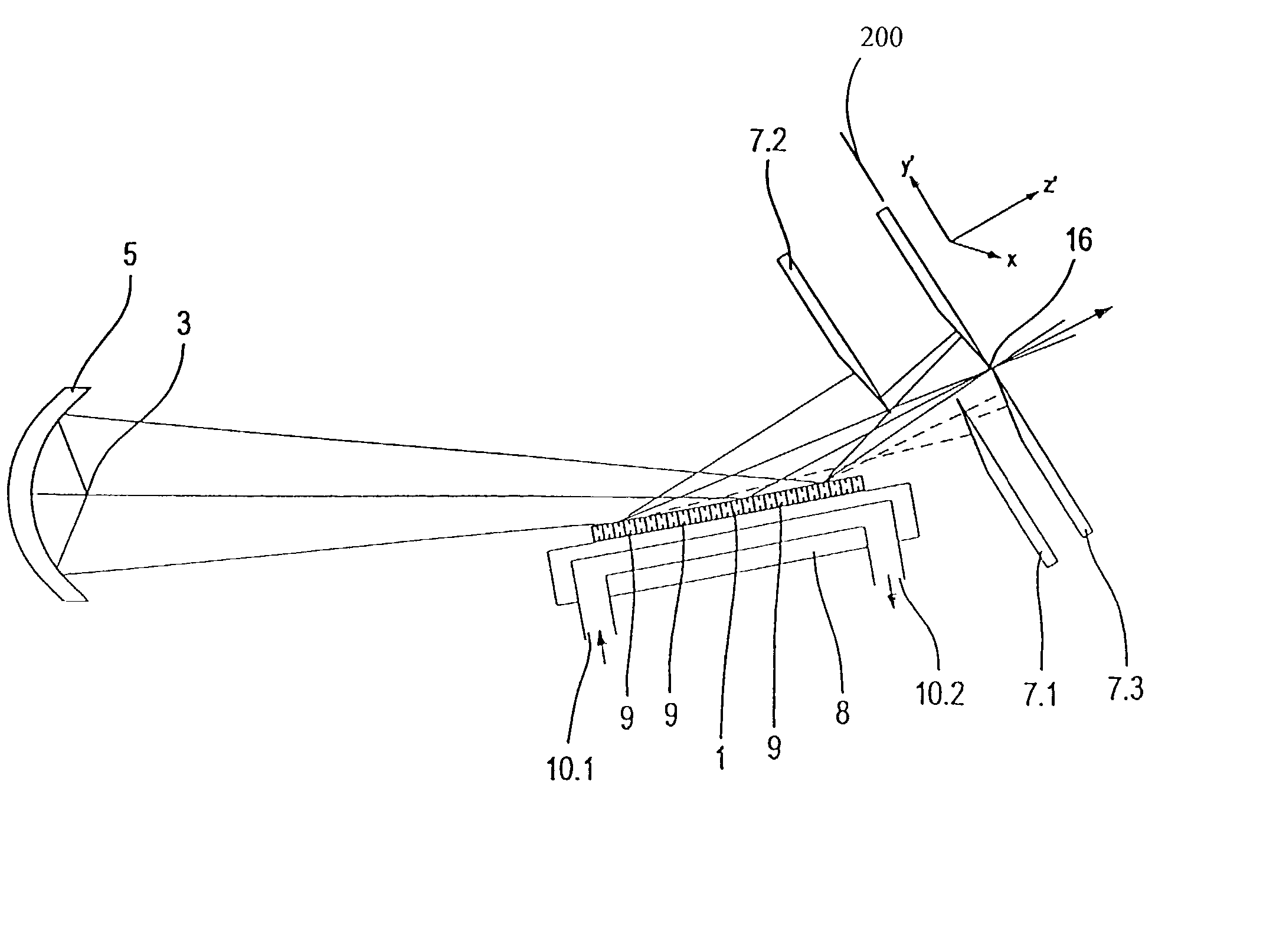
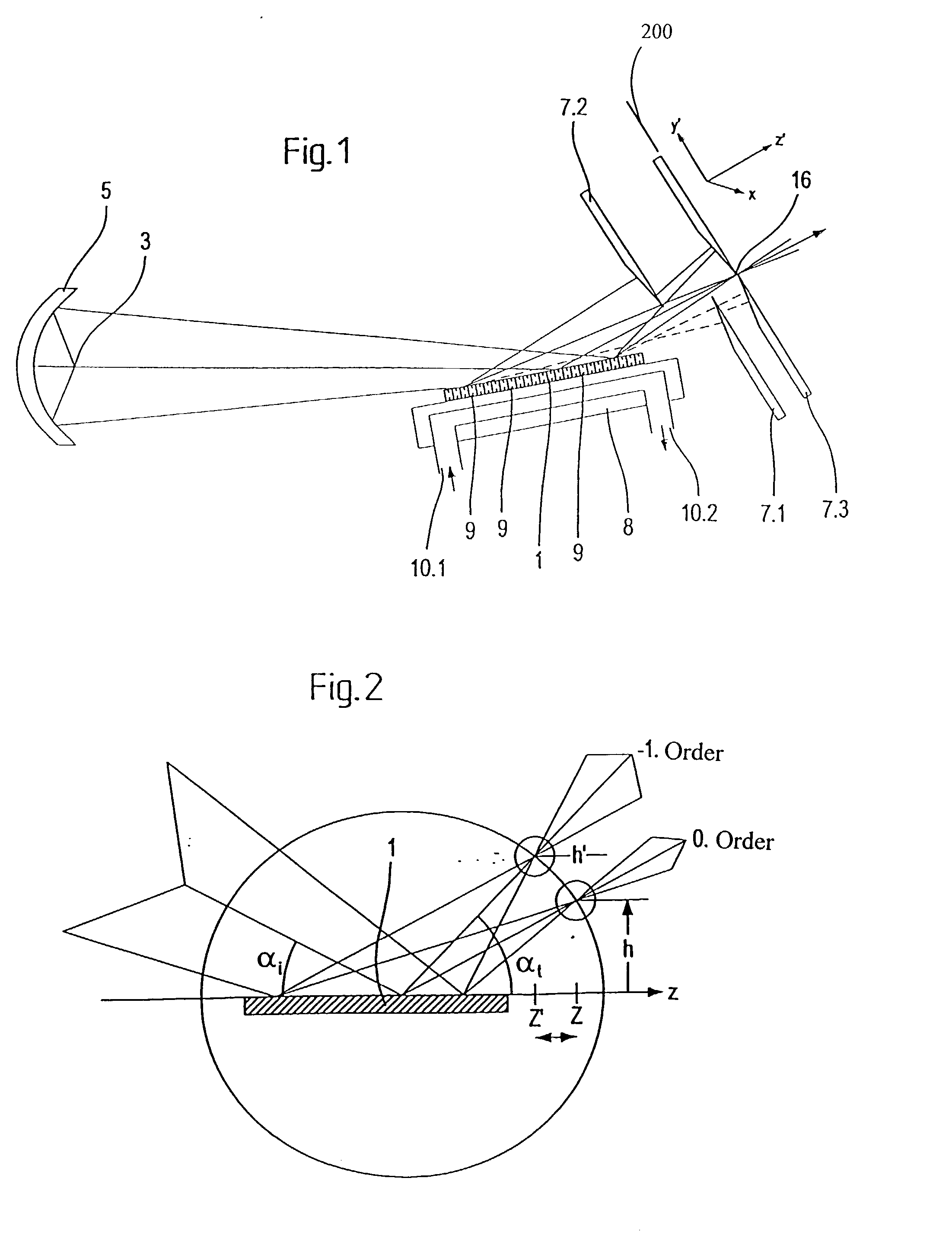
[0052] FIG. 1 shows a grating element 1 with a plurality of individual gratings 9 in a beam path of an illumination system. Individual gratings 9 are arranged one after the other in the beam direction. Light from a light source 3 is gathered by a collecting component, a collector 5. Collector 5 in this example is an ellipsoidal mirror, which produces an image of light source 3. A collimated light bundle with an aperture of around NA=0.1 is deflected in grazing incidence by grating element 1 after collector 5 so that an intermediate image of light source 3 comes to lie in or near a diaphragm plane 200 of a physical diaphragm, i.e., diaphragm 7.3.

[0053] By use of further physical diaphragms, i.e., diaphragms 7.1 and 7.2, arranged in front of diaphragm 7.3, a part of the unwanted radiation can be filtered out in order to reduce the heat load on diaphragm 7.3. Diaphragm 7.3 in one embodiment can have a circular opening. Diaphragm 7.3 is situated in a focal plane of a desired diffraction...


PUM


Abstract

There is provided an illumination system for wavelengths of <=100 nm, having an object plane and a field plane. The illumination system includes a grating element having a plurality of gratings, and a diaphragm. The diaphragm is arranged after the grating element in a beam path from the object plane to the field plane.

Description

[0001] The present application is claiming priority of German Patent Application Serial No. 101 27 449. 1, which was filed on Jun. 7, 2001.[0002] 1. Field of the Invention[0003] The invention concerns an illumination system for wavelengths of .ltoreq.100 nm, wherein the illumination system has an object plane and a field plane.[0004] 2. Description of the Prior Art[0005] In order to allow for further reduction in the structural widths of electronic components, especially in the submicron range, it is necessary to shorten the wavelength of the light used for microlithography. It is conceivable to use light with wavelengths of less than 100 nm, for example, lithography with soft x-rays, so-called EUV lithography.[0006] EUV lithography is one of the most promising future lithography techniques. At present, wavelengths in the range of 11-14 nm, especially 13.5 nm, are being considered as wavelengths for EUV lithography, with a numerical aperture of 0.2-0.3. The image quality in EUV lith...

Claims


Application Information

Patent Timeline
IPC IPC(8): G02B19/00G02B5/18G03F7/20G21K1/06H01L21/027
CPCG03F7/70158G21K1/06G03F7/702
Inventor SINGER, WOLFGANGWEISS, MARKUSKLEEMANN, BERNDOSTERRIED, KARLFRIEDWANGLER, JOHANNESMELZER, FRANKHEISLER, ANDREASBANINE, VADIM YEVGENYEVICH
Owner CARL ZEISS SMT GMBH
Why Eureka
Try Eureka