[0012]When the supporting frame for the center mold carrier element is attached to the
machine frame according to the invention, the center mold carrier element can be supported in a more massive and hence more robust rotary device, while on the other hand each of the two outer mold mounting plates moves back and forth directly and with a short displacement, i.e., without an intermediate moveable mold mounting plate, relative to the stationary supporting frame of the center mold carrier element.
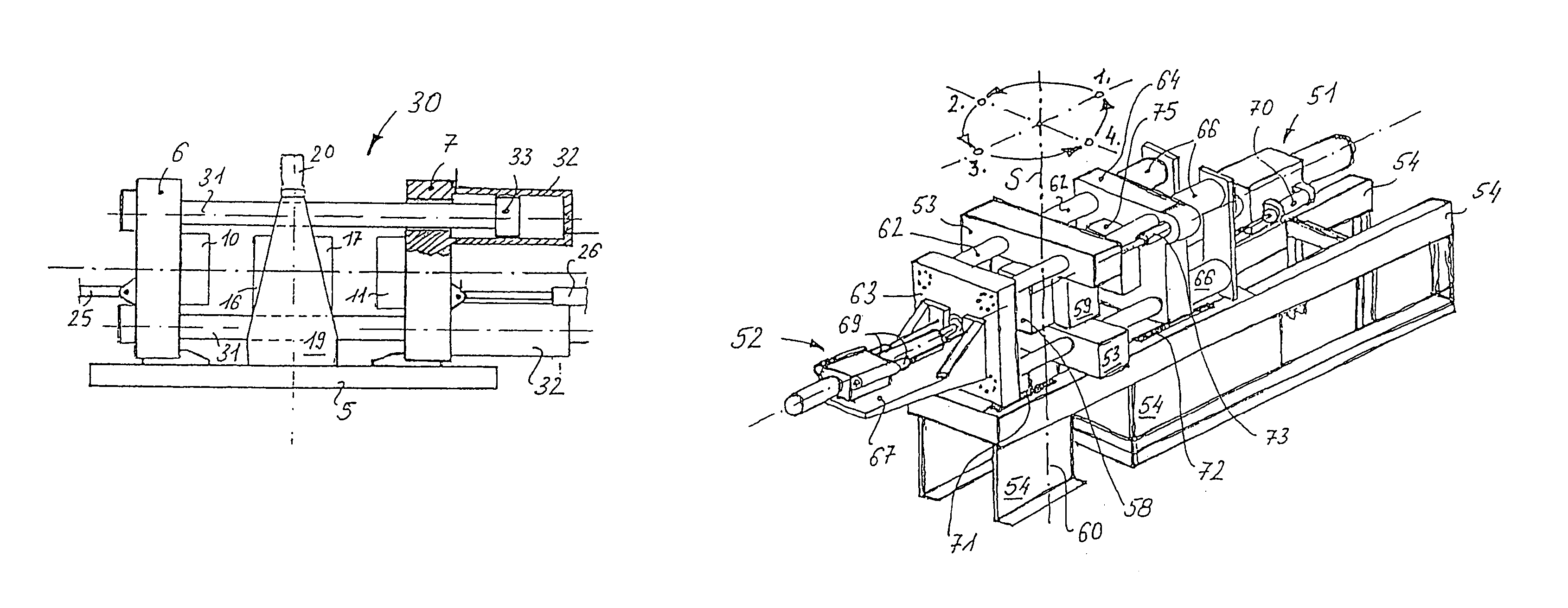
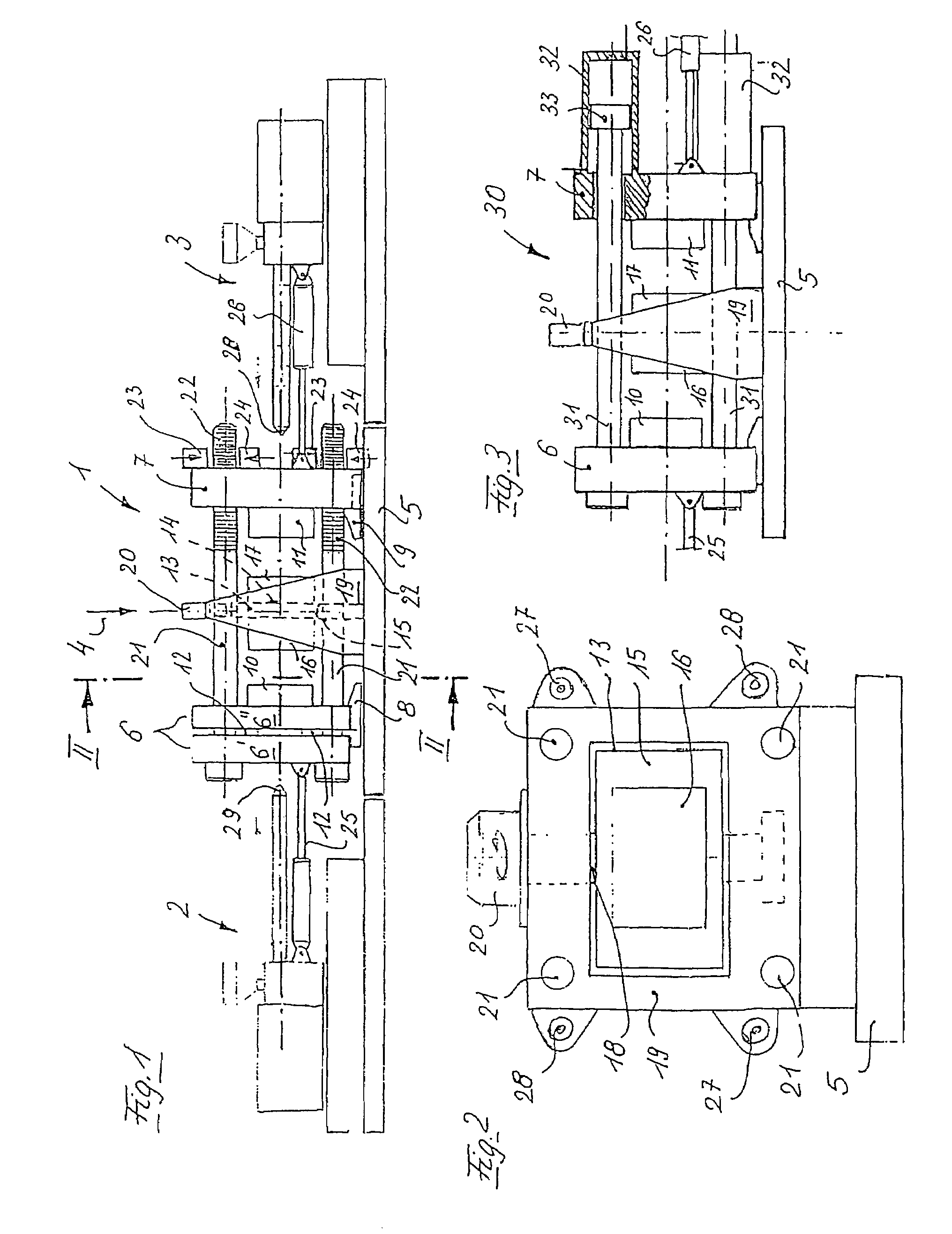
[0013]According to an advantageous feature of the invention, the columns of the mold closing device may be secured on one end to a support plate that is parallel to one of the outer mold mounting plates and penetrate on the other end the other outer mold mounting plate. The columns can be locked behind the mold mounting plate by saw tooth-shaped
interlocking elements. Advantageously, the support plate and the associated outer mold mounting plate form a sandwich plate with an interposed
hydraulic pressure piston. This plate arrangement has a very short construction and represents a particularly stiff
system because the quantity of
hydraulic fluid needs to be adequate only for producing the closing pressure. Larger quantities of hydraulic fluid which can increase the
compressibility thereby become unnecessary or are only used to operate the actuating drives (closing, loosening and opening), the motion of which is decoupled from the generation of the closing pressure. The aforedescribed two-plate closing
system with an interposed center mold carrying unit, which is fixedly supported in the machine frame, further enhances the stiffness of the mold closing device according to the invention substantially. This mold closing device can therefore advantageously be used to produce large multi-component plastic parts which require a highly precise machine, for example automobile glass, interior moldings for automobiles and multi-wall containers.
[0014]According to another advantageous feature of the invention, the columns may be secured on one end in an outer mold mounting plate and are formed on the other end as pistons, which are reversibly guided in cylinders that are fixedly connected with the other mold mounting plate. This two-plate closing system with an interposed center mold carrying unit, which is fixedly supported in the machine frame, advantageously also has a short construction and a
high stiffness.
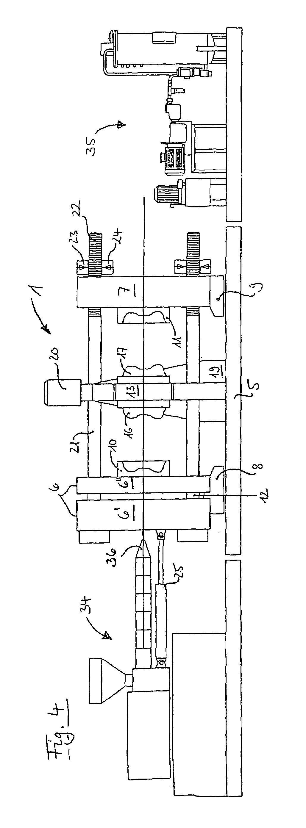
[0016]According to another advantageous feature of the invention, the supporting frame which is stationary in the machine frame can have a C-shape, i.e., can be provided with an opening to the loading / unloading side. In a mold carrier element shaped as a cube and having four mold halves, the basic component can be injection molded in a first cycle, as referenced to one of the four mold halves of the mold carrier element. In the second cycle, this component can cool down. In the third cycle, the basic component is finished into a two-component plastic part. In the fourth cycle, the mold half with the finished two-component plastic part is located in the open section of the C-shaped supporting frame and can be removed during the fourth cycle. Since the removal occurs during the fourth cycle, the
cycle time can be significantly shortened. In addition, inserts, for example metallic threaded sleeves or a plastic part, can advantageously be placed into the mold half after the finished two-component plastic part has been removed. Alternatively, the C-shaped frame can be operated so that the basic component is located during the second cycle on the open side of the frame, making it possible to perform an intermediate
processing step during the second cycle which otherwise would have to be performed during the first cycle. An exemplary
processing step, which typically can occur only after adequate cool-down of the plastic part, can be a surface treatment of the basic component to improve adhesion between the plastic material molded in the following step and the basic component. Such
processing step is useful for bonding a
thermoplastic basic component with a 2-component Thermosetting plastic
coating, in particular a
polyurethane coating and other like, and can be performed, for example, by a
robot located on the side of the mold closing device. In particular, a mold carrier element with four or six mold halves shortens the
cycle time. The open C-shaped supporting frame can also be used with a mold carrier element that has only two mold halves, since the mold mounting areas can be rotated to the open section of the supporting frame to allow a mold change or for maintenance work. The particularly short construction of the mold closing devices of the invention can overcome the more difficult access to the center mold halves associated with this design.

