Array antenna device and radio communication device

a radio communication device and antenna device technology, applied in the field of array antenna devices, can solve the problems of achieve the effect of difficult to increase a radiation angle and high cost of a dielectric material for low loss

Inactive Publication Date: 2016-03-10
PANASONIC CORP
View PDF2 Cites 133 Cited by
  • Summary
  • Abstract
  • Description
  • Claims
  • Application Information

AI Technical Summary

Benefits of technology

[0008]One non-limiting and exemplary embodiment provides an array antenna device which is capable of radiating a radio wave in lower loss and increasing a radiation angle, and which can be more simply manufactured, compared to a conformal antenna composed of a planar antenna.
[0011]The array antenna device according to one aspect of the present disclosure is capable of radiating a radio wave in lower loss and increasing a radiation angle, compared to a conformal antenna which is composed of a planar antenna.

Problems solved by technology

However, compared to the waveguide array antennas which are disclosed in Japanese Unexamined Patent Application Publication Nos. 7-176948, 6-188925, and 7-106847, the cost of a dielectric material for low loss is high and it is difficult to increase a radiation angle.

Method used


Image

  • Array antenna device and radio communication device
  • Array antenna device and radio communication device
  • Array antenna device and radio communication device

Examples


embodiment 1

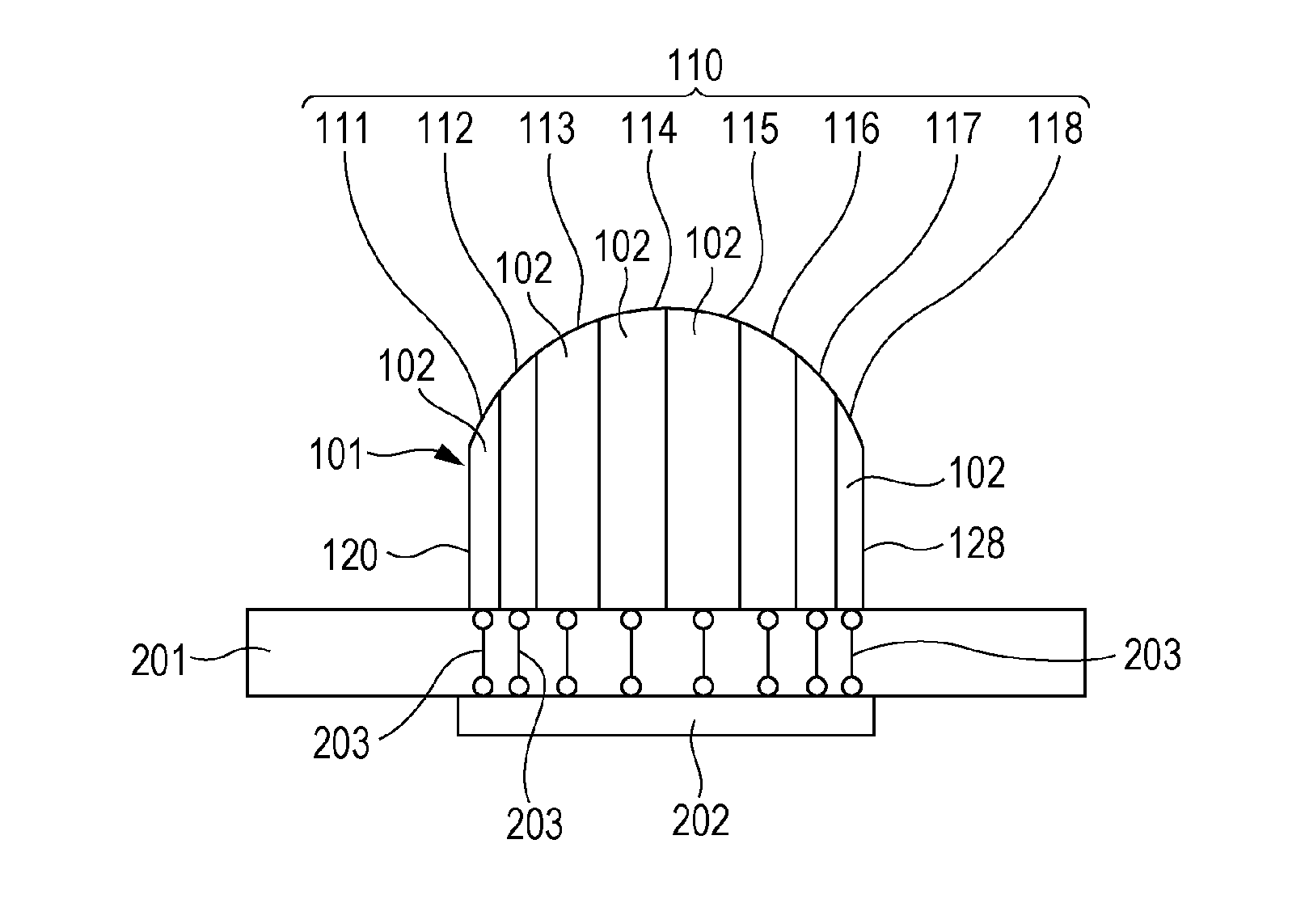
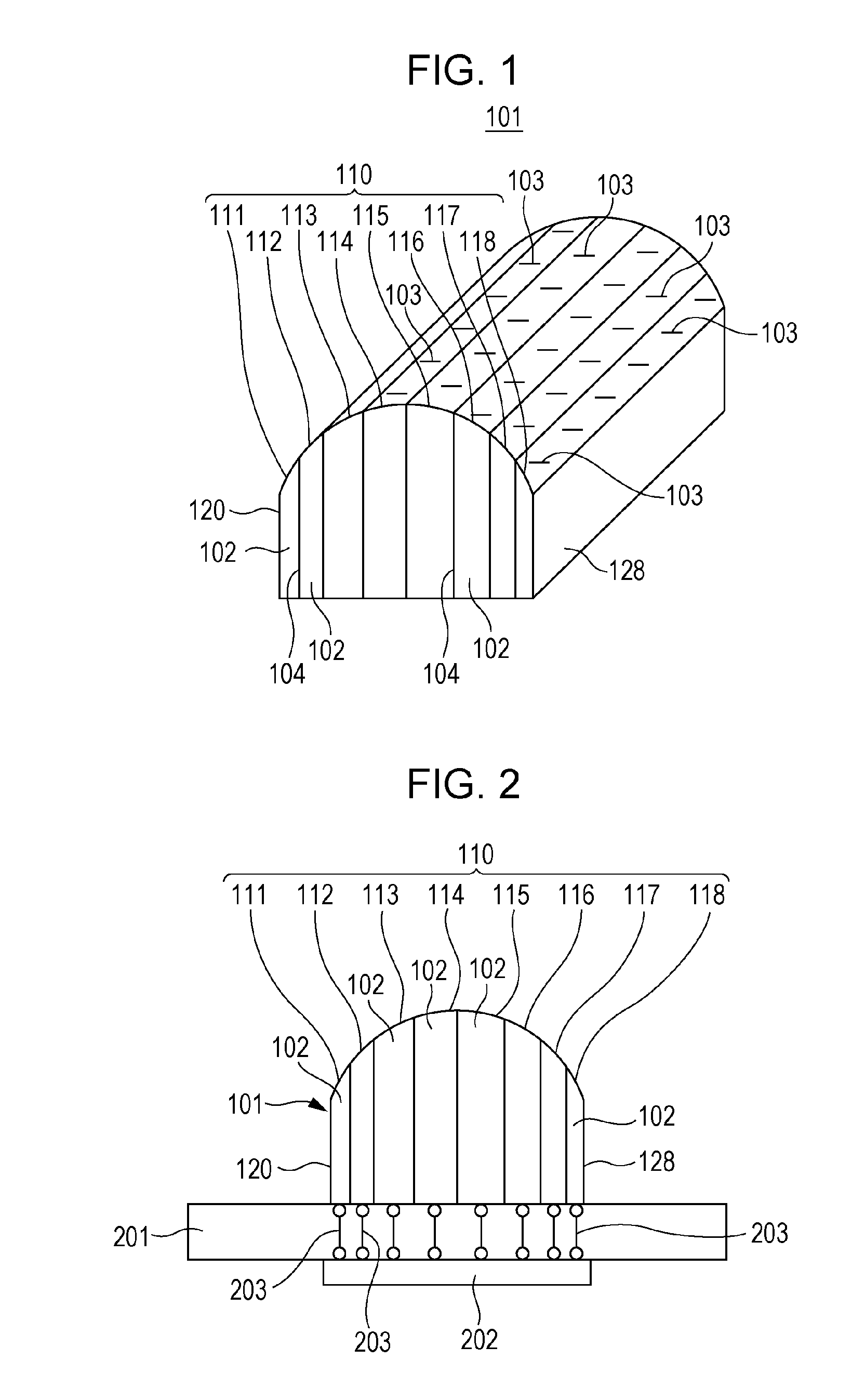
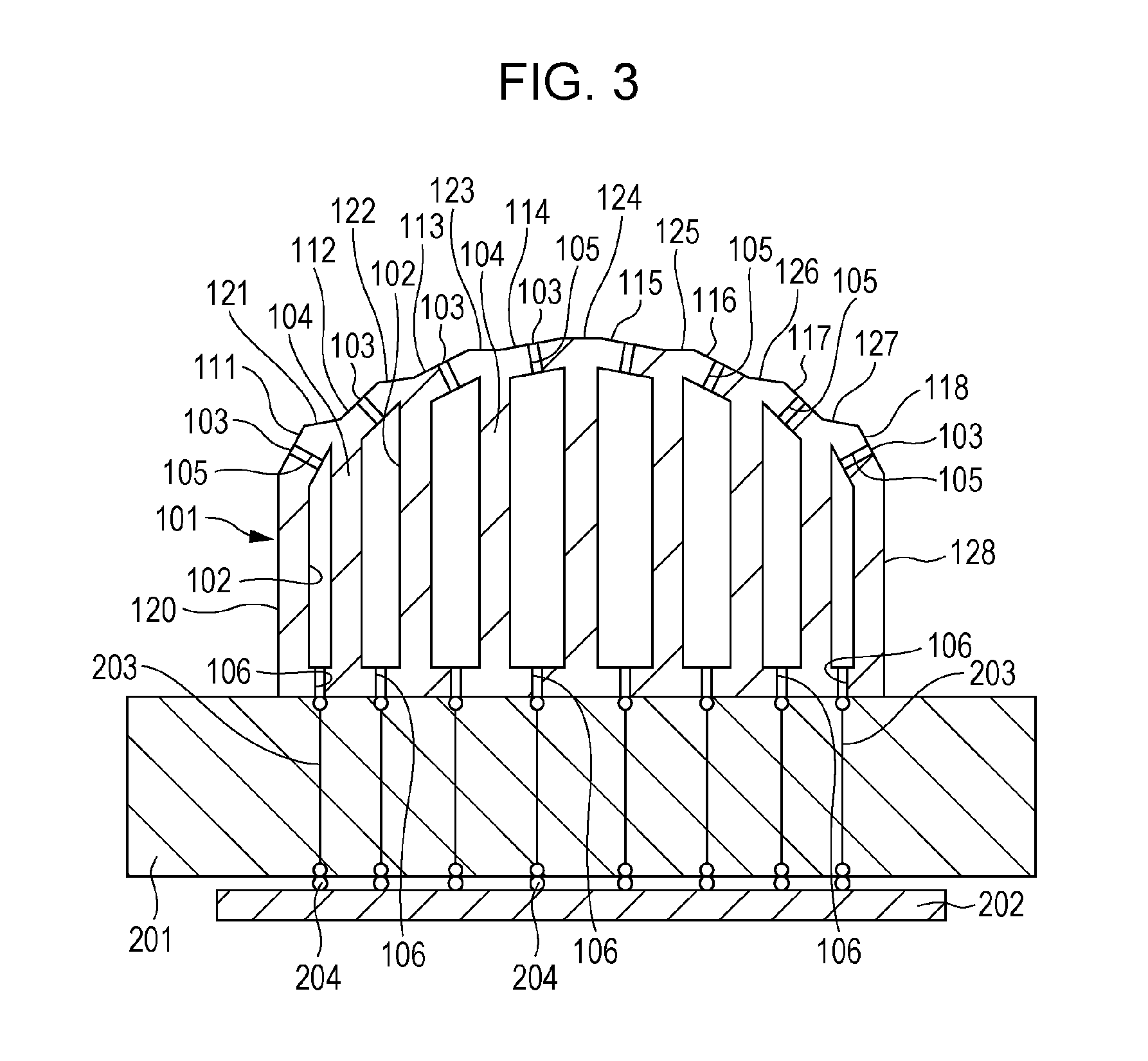
[0028]FIG. 1 is a perspective view illustrating an external appearance of a conformal waveguide slot array antenna device 101 according to Embodiment 1. The conformal waveguide slot array antenna device 101 according to the present embodiment is composed of a plurality of slot array antennas which are arranged. Each of the plurality of slot array antennas includes a plurality of slot antennas 103 which are formed on each of narrow wall surfaces 111 to 118 constituting a radiation surface 110 which is formed in a conformal shape to have curvature like that of a body of an airplane, for example. Here, the radiation surface 110 is composed of a plurality of narrow wall surfaces 111 to 118 which have a rectangular flat plate shape, for example. The lower portion of the radiation surface 110 is composed of a plurality of rectangular waveguides 102 which are separated by lateral walls 104 between lateral wide wall surfaces 120 and 128. A radio signal supplied to each of the rectangular wa...

embodiment 2

[0056]FIG. 12 is a perspective view illustrating an external appearance of a radar device 300 according to Embodiment 2. The radar device 300 according to Embodiment 2 is configured to include two pieces of conformal waveguide slot array antenna devices 101 according to Embodiment 1 as shown in FIG. 12. The two pieces of conformal waveguide slot array antenna devices 101 are respectively used as a transmission antenna 101T and a reception antenna 101R. A radio frequency (RF) module for the radar device 300 is configured such that the transmission antenna 101T and the reception antenna 101R are aligned on a substrate 310 and a radio transmission circuit 321 shown in FIG. 13 and a radio reception circuit 322 shown in FIG. 14 are provided on a lower portion of the substrate. This radar device 300 is used for collision avoidance of vehicles, for example. The radar device 300 transmits a radio signal by using a radio wave in a sub-millimeter wave or millimeter wave band, for example, and...


PUM


Abstract

An array antenna device includes a plurality of slot array antennas which are arranged and each of which includes a plurality of slot antennas and a radiation surface, which is formed to be conformal, and a plurality of waveguides each of which supplies respective power to each of the slot array antennas. After bodies of the waveguides are formed by a resin molding method, surface treatment is performed with respect to inner surfaces of the waveguides with plating.

Description

BACKGROUND[0001]1. Technical Field[0002]The present disclosure relates to an array antenna device such as a conformal waveguide slot array antenna device and a radio communication device using the array antenna device.[0003]2. Description of the Related Art[0004]An example of a conformal antenna is disclosed in Japanese Unexamined Patent Application Publication No. 63-031304, for example. This conformal antenna is characterized in that “in an antenna device including an antenna base which has a desired curved surface, microstrip antennas which are attached in a predetermined pitch on an outer circumference of the base, and a power supply circuit which is disposed in one of an inside and an outside of the antenna base and supplies a radio wave to the microstrip antennas, a thickness of radiation conductor elements, among a dielectric substrate, a plurality of pieces of connectors, and the radiation conductor elements constituting the microstrip antenna, is changed so as to form a par...

Claims


Application Information

Patent Timeline
Patent Type & Authority Applications(United States)
IPC IPC(8): H01Q1/24H01Q13/10H01Q1/50
CPCH01Q13/10H01Q1/50H01Q1/24H01Q13/20H01Q21/005H01Q21/20
Inventor IWAI, HIROSHISATO, JUNJISHIOZAKI, RYOSUKEHIROKAWA, JIROZHANG, MIAO
Owner PANASONIC CORP
Why Eureka
Try Eureka