Flashlight with drop-in side-by-side batteries

a side-by-side battery and flashlight technology, applied in the field of flashlights, can solve the problems that not all flashlights are used, and achieve the effects of convenient battery insertion, convenient battery polarization, and convenient battery insertion

Inactive Publication Date: 2006-02-16
UNDERWATER KINETICS
View PDF25 Cites 14 Cited by
  • Summary
  • Abstract
  • Description
  • Claims
  • Application Information

AI Technical Summary

Benefits of technology

[0007] The present invention concerns a flashlight that uses batteries in a side-by-side arrangement where the batteries can be inserted in a simple drop-in manner and where the flashlight includes features that allow more convenient battery insertion and / or provide battery polarization. Configurations that include the feature allowing more convenient battery insertion thus avoid the difficulties involved in inserting and removing batteries when spring compression or the like is needed to place and / or hold the batteries in proper position. This is accomplished by using a pivoting electrical connector that has an off-set pivot point. That pivoting connector, termed a pivot contact, is located at the rear of the battery chamber in the flashligh housing, and provides an electrical connection between two side-by-side rows of batteries. The off-set pivot provides a lever with unequal length lever arms, so that pressing a row of batteries against the short arm of the pivoting connector (such as by screwing on a bezel containing a reflector assembly with a light bulb) causes movement of the short arm and a corresponding a larger movement of the longer arm. Using this construction, the pivoting connector can pivot out of the way to allow an initial row of batteries to drop into place in line with the longer arm of the connector without interference, but still allow positive contact to be made when the flashlight is closed. In configurations that include battery polarization, electrical contacts within the flashlight are designed such that an electrical path to energize a light source will only occur if the batteries are inserted with correct polarity. Such polarization can be used together with a pivot having on off-center pivot contact or separately.
[0009] Likewise, the invention provides a flashlight that includes a battery housing that has a front end and a rear end, where the housing is configured to accept a plurality of batteries in a side-by-side configuration such that there are adjacent first and second rows of batteries, a light source assembly at the front end, electrical connections for providing electrical power from the batteries to a light source in the light source assembly, and a pivot contact at the rear end providing an electrical connection between a battery in the first row to a battery in the second row. The connector includes a support with a pivot and a conductive material configured to provide an electrical path between said adjacent rows of batteries. The flashlight is configured to provide battery polarization such that only if the batteries are inserted with correct polarity will an electrical circuit be established to energize the light source.
[0027] In yet another related aspect, the invention provides a method for providing battery polarization in a battery-pwered electrical device by utilizing a battery polarizer as described herein in the electrical device. As indicated above, the battery polarizer can be constructed as part of a pivot contact as described above, thereby providing both ease of battery insertion and battery polarization in a device.

Problems solved by technology

However, not all flashlights use the linear battery arrangement.

Method used


Image

  • Flashlight with drop-in side-by-side batteries
  • Flashlight with drop-in side-by-side batteries
  • Flashlight with drop-in side-by-side batteries

Examples


Embodiment Construction

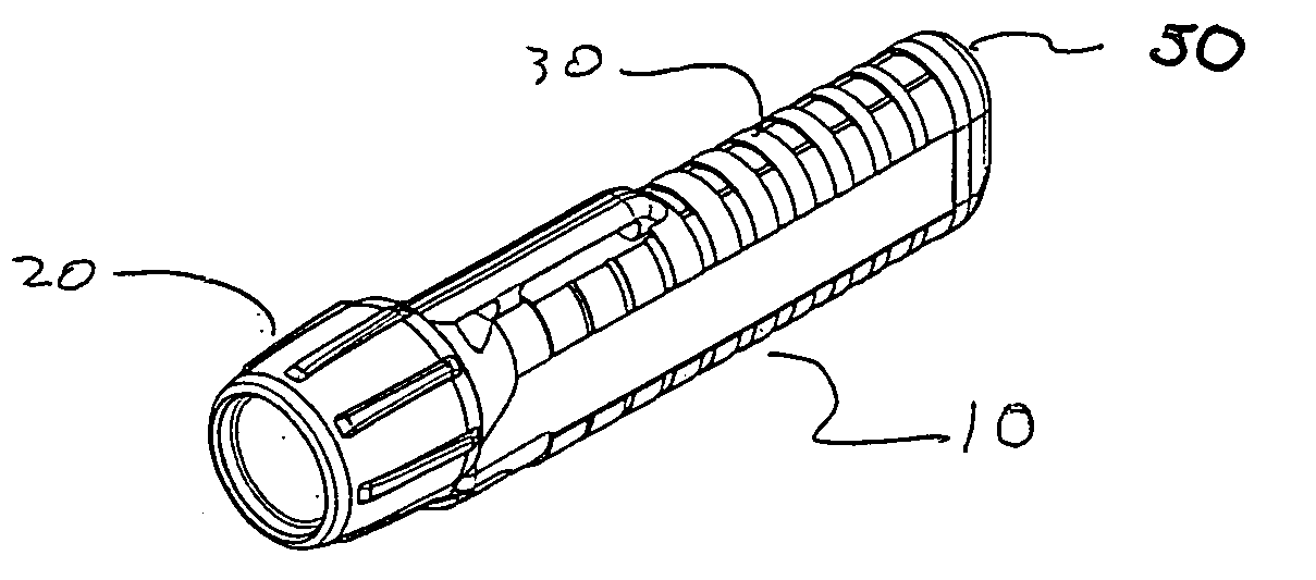
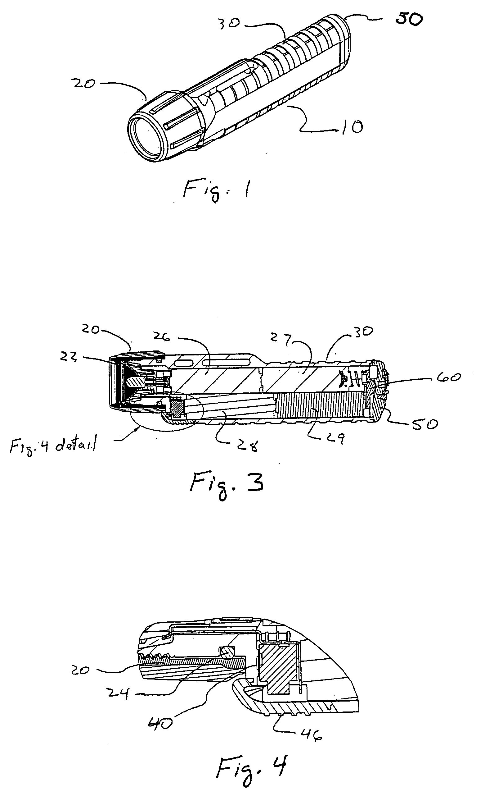
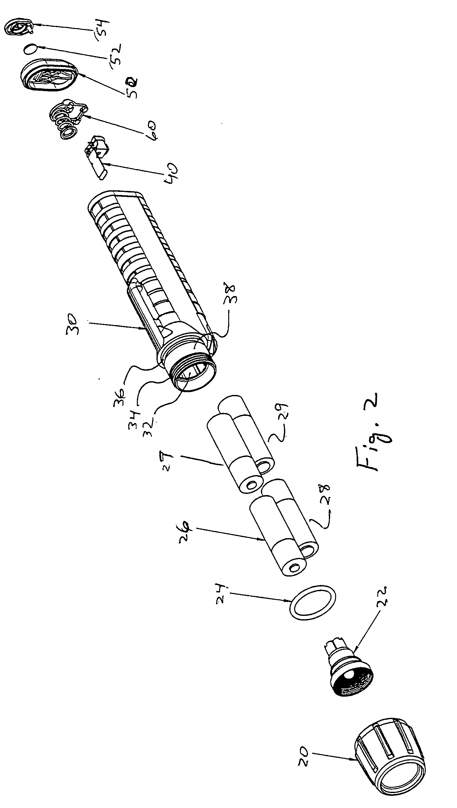
[0036] The present invention provides a flashlight that utlizes a side-by-side battery configuration in which the batteries are easily inserted and removed and / or that includes battery polarization. The ease with which the batteries are inserted and removed is due to the design of a pivoting contact piece (pivot contact) located in the rear of the battery housing. Alternatively, or in addition, the flashlight can be constructed to provide battery polarization, such that an electrical circuit will not be established unless the batteries are inserted in the flashlight with correct polarity, i.e., with correct orientation of positive and negative terminals. In addition, the flashlight can be constucted such that the flashlight is well-adapted for use in hazardous environments and further can be made waterproof.

[0037] A number of features can provide the adaptations for use in hazardous environments. These can, for example, include battery polarization. It is also beneficial to provide...


PUM


Abstract

A battery powered flashlight is described that has a pivot contact with an off-center pivot point and / or battery polarization is described. The flashlight is configured to allow batteries to be dropped into place without interference with internal flashlight components.

Description

CROSS-REFERENCE TO RELATED PATENT APPLICATIONS [0001] {ENTER Not applicable or related application information.}BACKGROUND OF THE INVENTION [0002] The present invention relates to the field of battery powered flashlights, and especially to flashlights suitable for use in highly flammable or explosive environments. [0003] The information provided herein and references cited is intended soley to assist the understanding of the reader. None of the information provided or references cited is admitted to be prior art to the present invention. [0004] A large number of different flashlight designs have been described with various configurations. Most flashlights have generally cylindrical hollow housings that contain one or more cylindrical batteries in a single row. When a plurality of batteries are used, the positive terminal of the battery most distal from the light source contacts the negative terminal of the adjacent battery, continuing in this manner so that the positive terminal of ...

Claims


Application Information

Patent Timeline
Patent Type & Authority Applications(United States)
IPC IPC(8): F21L4/00
CPCF21V25/12F21L4/005
Inventor UKE, ALAN K.
Owner UNDERWATER KINETICS
Why Eureka
Try Eureka