Menu image display method and electronic information equipment

a technology of electronic information equipment and menus, applied in the direction of television systems, instruments, color signal processing circuits, etc., can solve the problems of inconvenient use, user difficulty in reading, and inability to recognize each item clearly, and achieve the effect of easy recognition

Inactive Publication Date: 2006-03-16
VICTOR CO OF JAPAN LTD
View PDF6 Cites 98 Cited by
  • Summary
  • Abstract
  • Description
  • Claims
  • Application Information

AI Technical Summary

Benefits of technology

[0013] In view of the foregoing, it is an object of the present invention to provide a menu image display method and electronic information equipment that allow the user to easily recognize at which hie

Problems solved by technology

Meanwhile, in the conventional menu image display method, if small-letter information is displayed on the display (display screen) such as the one installed in portable information equipment that is an example of electronic information equipment, the user finds it difficult to read and inconvenient to use.
A problem to be solved is to present hierarchically structured se

Method used


Image

  • Menu image display method and electronic information equipment
  • Menu image display method and electronic information equipment
  • Menu image display method and electronic information equipment

Examples


first embodiment

[0057] A first embodiment will be described with portable information equipment, such as a video camera, as an example of electronic information equipment.

[0058]>

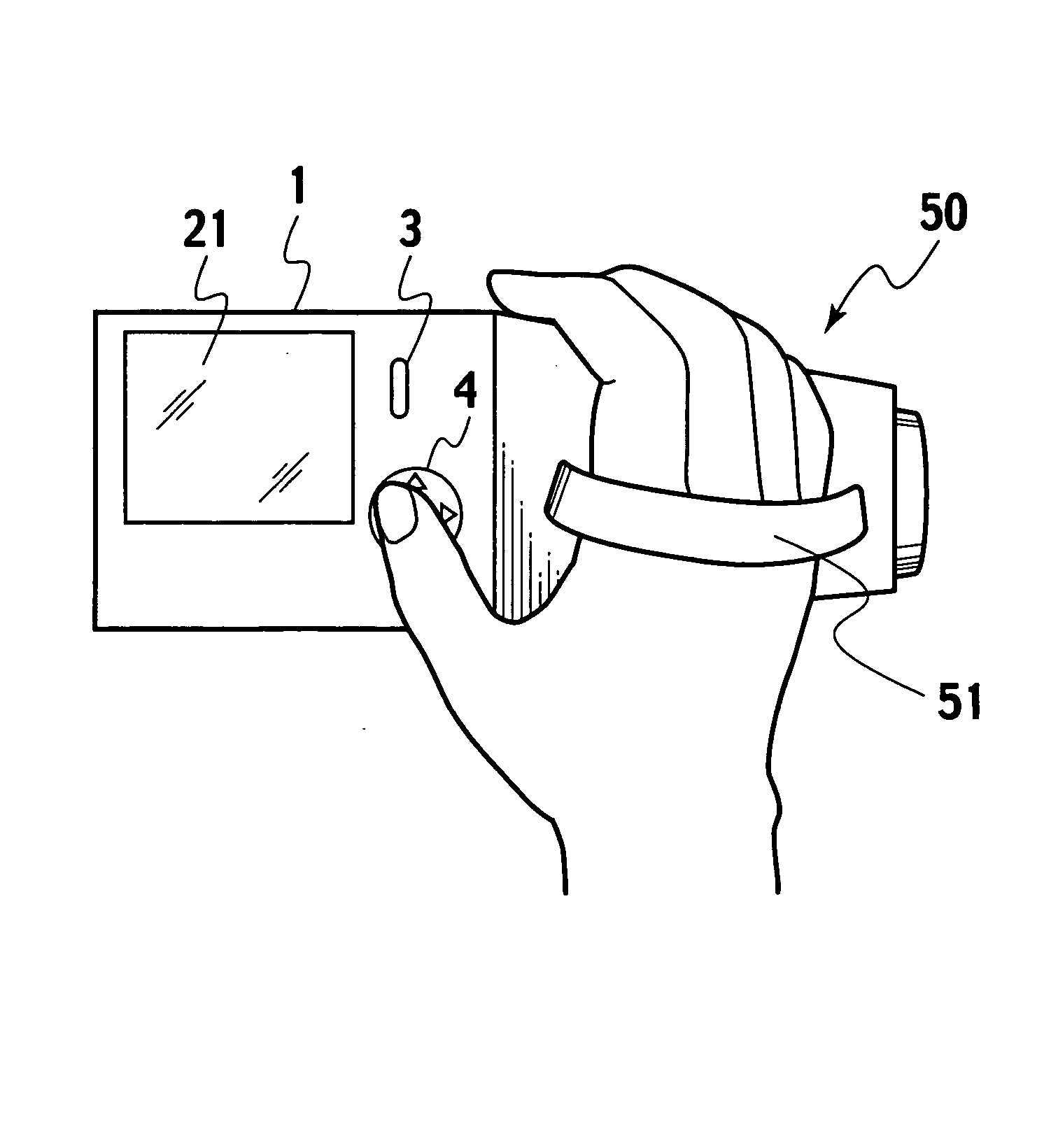
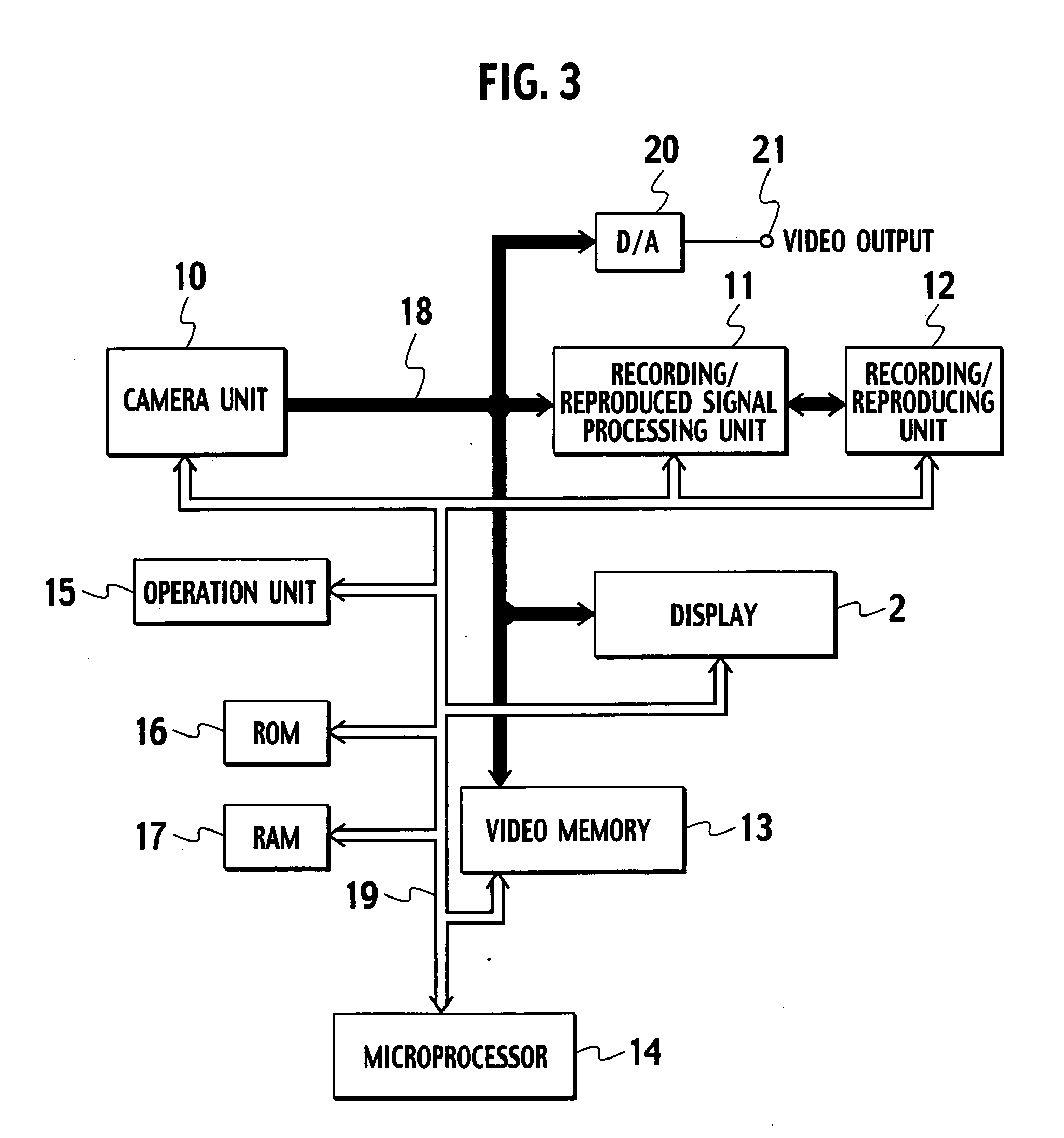
[0059]FIG. 3 shows an example of the hardware configuration of portable information equipment. The blocks shown in the figure are included in a shooting-type video camera 50 such as the one shown in FIG. 7. Referring to FIG. 3, a video shot by a camera unit 10 is converted by the camera unit 10 into a digital signal and, via a video signal bus 18, supplied to a recording / reproduced signal processing unit 11. The recording / reproduced signal processing unit 11 compresses and formats the received digital signal and supplies the digital signal to a recording / reproducing unit 12. The recording / reproducing unit 12 includes or stores a magnetic tape such as a DVC (Digital Video Cassette), a hard disk built-in card such as a Microdrive (registered trademark), a semiconductor memory card such as an SD card (registered trademark), o...

second embodiment

[0099] A second embodiment, an extension of the menu image display method in the first embodiment, allows the user to better understand the relation among the first hierarchical level to the third hierarchical level. The actual configuration of electronic information equipment for implementing the second embodiment is the same as that shown in FIG. 3. With reference to FIG. 14, the following describes only the characteristic part of the second embodiment.

[0100]FIG. 14A shows a first hierarchical level similar to that shown in FIG. 4, FIG. 14B shows a second hierarchical level menu similar to that shown in FIG. 5, and FIG. 14C shows third hierarchical level information similar to that shown in FIG. 6. The information at the third hierarchical level is not a thumbnail image such as the one shown in FIG. 6 but the setting information corresponding to the selected items (“Moving image quality” in this example).

[0101] The second embodiment is different from the first embodiment in the ...

third embodiment

[0106] The first to third hierarchical levels are sequentially moved horizontally in the first and second embodiments, while the first to third hierarchical levels are sequentially moved diagonally in a third embodiment. The third embodiment is basically the same as the first embodiment. With reference to FIG. 15, the following describes only the characteristic parts of the third embodiment. FIG. 15 shows the display state at the second hierarchical level similar to that shown in FIG. 5.

[0107] Referring to FIG. 15, the display screen 21 is divided by boundary lines B31 and B32 into three areas. The lower left corner is area R31, the upper right corner is area R33, and the part between boundary line B31 and boundary line B32 is area R32. Triangle mark S31 is displayed in area R31, triangle mark S32 is displayed in area R33, and the menu items at the second hierarchical level are displayed in area R32. The transition from this state to the first hierarchical level is done by moving i...


PUM


Abstract

When a menu image transition occurs from a first hierarchical level to a second hierarchical level and to a third hierarchical level, boundary lines B1 and B2, which are near but not in contact each other, are displayed on a display screen to divide it into three areas, R1, R2, and R3. A triangle mark is displayed in area R1 to indicate that there is a higher hierarchical level. Areas R1 and R2 allow the user to recognize that there are the first and second hierarchical levels which are higher. Information (for example, thumbnail images) corresponding to the third hierarchical level is displayed in area R3.

Description

BACKGROUND OF THE INVENTION [0001] 1. Field of the Invention [0002] The present invention relates to a menu image display method and electronic information equipment, and more particularly to a menu image display method and electronic information equipment that allows the user to easily recognize at which hierarchical level the user is currently performing operation in a hierarchically structured menu. [0003] The present invention is widely applicable when the user performs operation on portable information equipment such as a video camera, a cellular phone, or a portable information terminal or on other various types of electronic information equipment, with a menu image of multiple hierarchy levels displayed on the screen. [0004] 2. Description of the Related Art [0005] As one of typical examples of conventional operation that uses a display screen, the following describes an operation on a personal computer. FIG. 1 shows the configuration of a screen used for various settings or ...

Claims


Application Information

Patent Timeline
IPC IPC(8): H04N5/228H04N5/222H04N5/445H04N9/64H04N5/66G06F3/0482G06F3/0485
CPCG06F3/0482H04N2101/00H04N1/00424H04N1/00432H04N1/0044H04N1/00453H04N1/00472H04N1/00474H04N5/23293H04N5/45H04N5/772H04N5/775H04N5/781H04N5/85H04N5/907H04N9/8042H04N9/8205H04N9/8715H04N1/00397H04N23/631H04N23/635G06F3/14G06F9/00G06F3/00
Inventor JIN, AKIYOSHIOTSUKA, KUNIONOGUSHI, NAOYUKITAKITA, SOUSHI
Owner VICTOR CO OF JAPAN LTD
Why Eureka
Try Eureka