Image heating apparatus including flexible metallic sleeve, and heater used for this apparatus

a heating apparatus and flexible technology, applied in the field of image heating apparatus, can solve the problems of reducing the durability of the glass layer, reducing the tear strength of the fixing film, and affecting the heating effect of the heating apparatus,

Inactive Publication Date: 2006-03-16
CANON KK
View PDF36 Cites 25 Cited by
  • Summary
  • Abstract
  • Description
  • Claims
  • Application Information

AI Technical Summary

Problems solved by technology

When the base layer of the fixing film 3 is made of a metal such as SUS, however, the durability of the glass layer is reduced.
However, when too large an amount of heat conductive filler is mixed into the resin, the tear strength of the fixing film is reduced and tearing of the film will occur.
It has been found, however, that when coping with an increase in the processing speed of an image forming apparatus, merely making the slide layer of the heater of a resin such as polyimide is not sufficient.
However, increasing the pressuring force and raising the temperature of the heater both tend to accelerate the abrasion of the slide layer of the heater.
As a result, the desired viscosity and smoothness of the grease is lost, the resistance produced by friction is increased, and the drive torque becomes greater.
When the drive torque is increased, it is difficult to rotate the fixing film at high speed, and the processing capability of the fixing apparatus can not be improved.
And when a thick slide layer is formed, although the durability of the slide layer is increased, the heat generated by the heater is not easily transmitted to the nip portion.
Thus, the method employed to increase the thickness of the slide layer is also not acceptable.

Method used


Image

  • Image heating apparatus including flexible metallic sleeve, and heater used for this apparatus
  • Image heating apparatus including flexible metallic sleeve, and heater used for this apparatus
  • Image heating apparatus including flexible metallic sleeve, and heater used for this apparatus

Examples


first embodiment

[0045] (1) Explanation of an Image Forming Apparatus

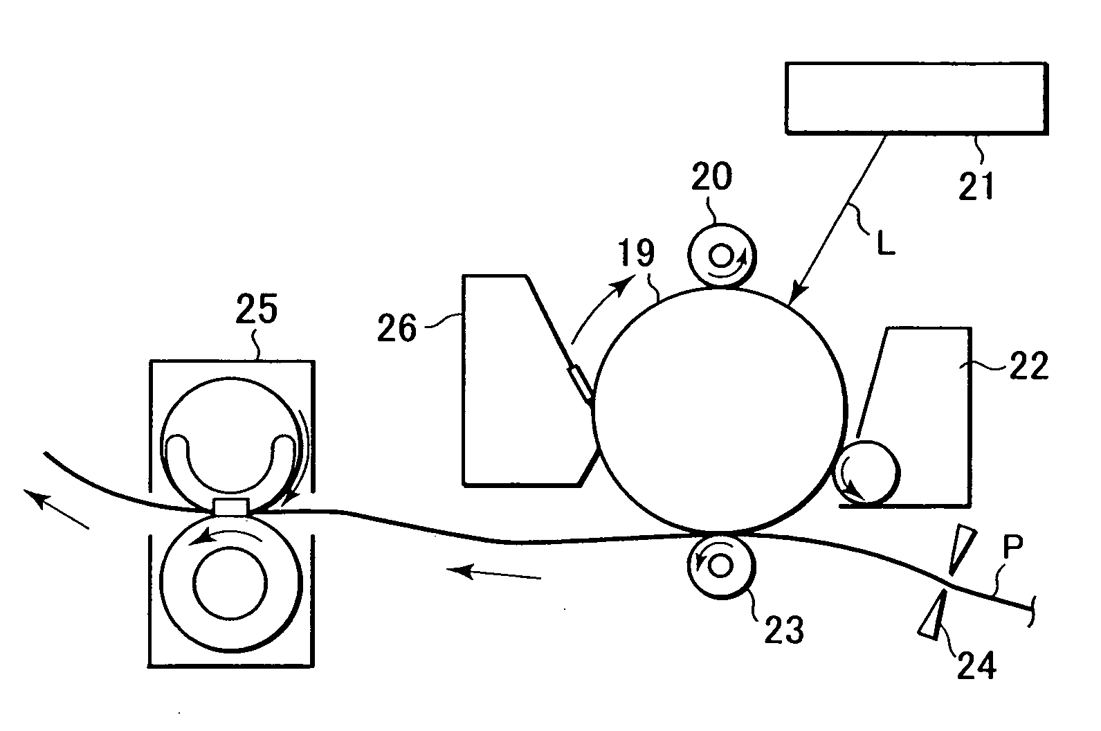
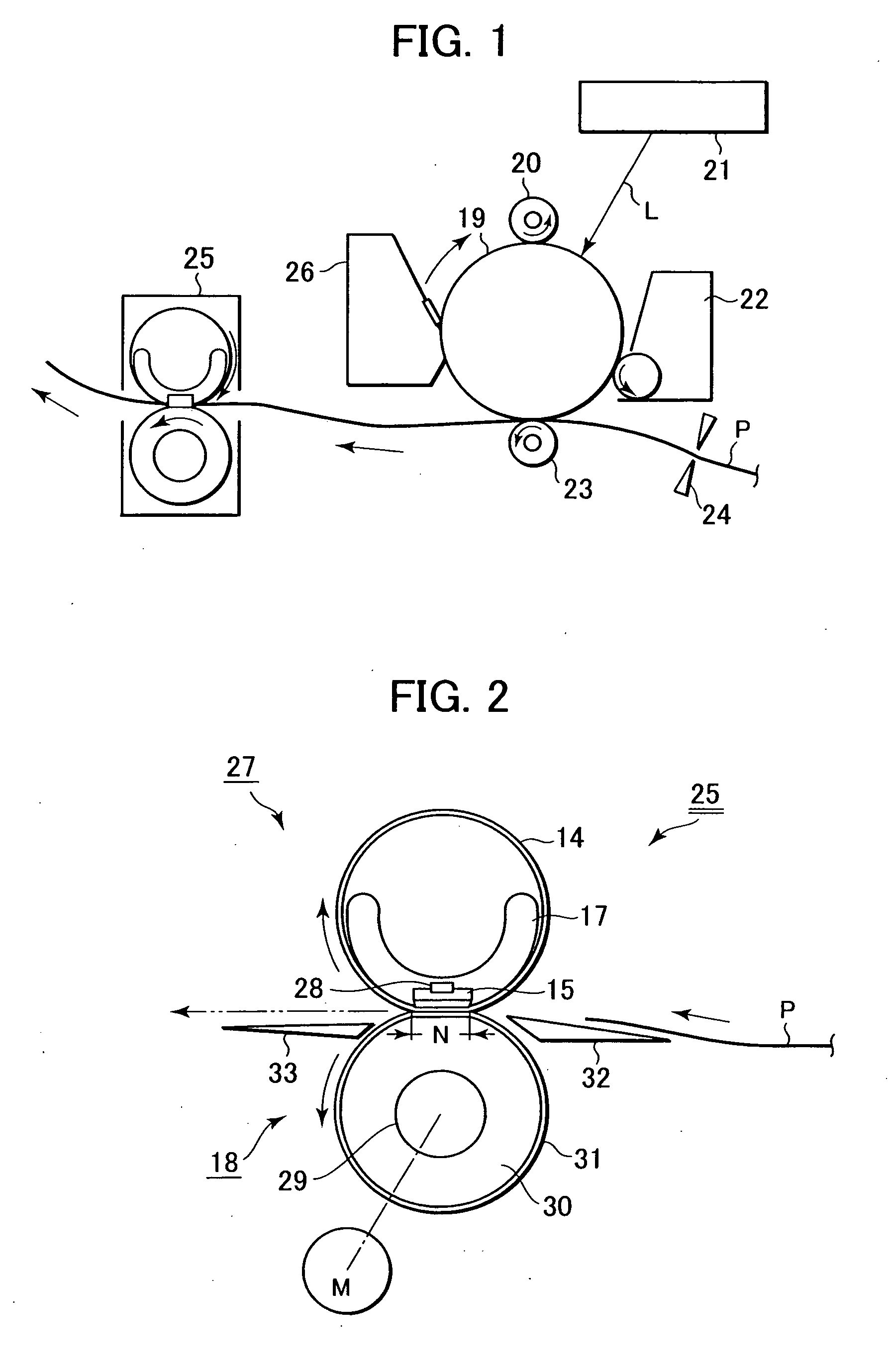
[0046]FIG. 1 is a schematic diagram showing the configuration of an image forming apparatus in which is mounted an image heating apparatus according to a first embodiment of the invention. The image forming apparatus in this embodiment is a laser printer employing an electrophotographic process.

[0047] A photosensitive drum 19 is made by depositing a photosensitive material, such as amorphous Se or amorphous Si, on an aluminum or nickel cylinder substrate.

[0048] First, the photosensitive drum 19 is rotated in the direction indicated by an arrow, and the surface of the photosensitive drum 19 is uniformly electrified by a charging device, a charge roller 20.

[0049] Then, the uniformly charged surface of the photosensitive drum 19 is exposed using a laser scanner unit 21, and an electrostatic latent image, according to an image information, is formed on the photosensitive drum 19. A laser beam L, which scans the photosensitive drum ...

second embodiment

[0112] A second embodiment of the present invention will now be described. Since the overall configuration of the image forming apparatus and the overall configuration of the thermal fixing apparatus for this embodiment are the same as those for the first embodiment explained while referring to FIGS. 1 and 2, no further explanation for them will be given.

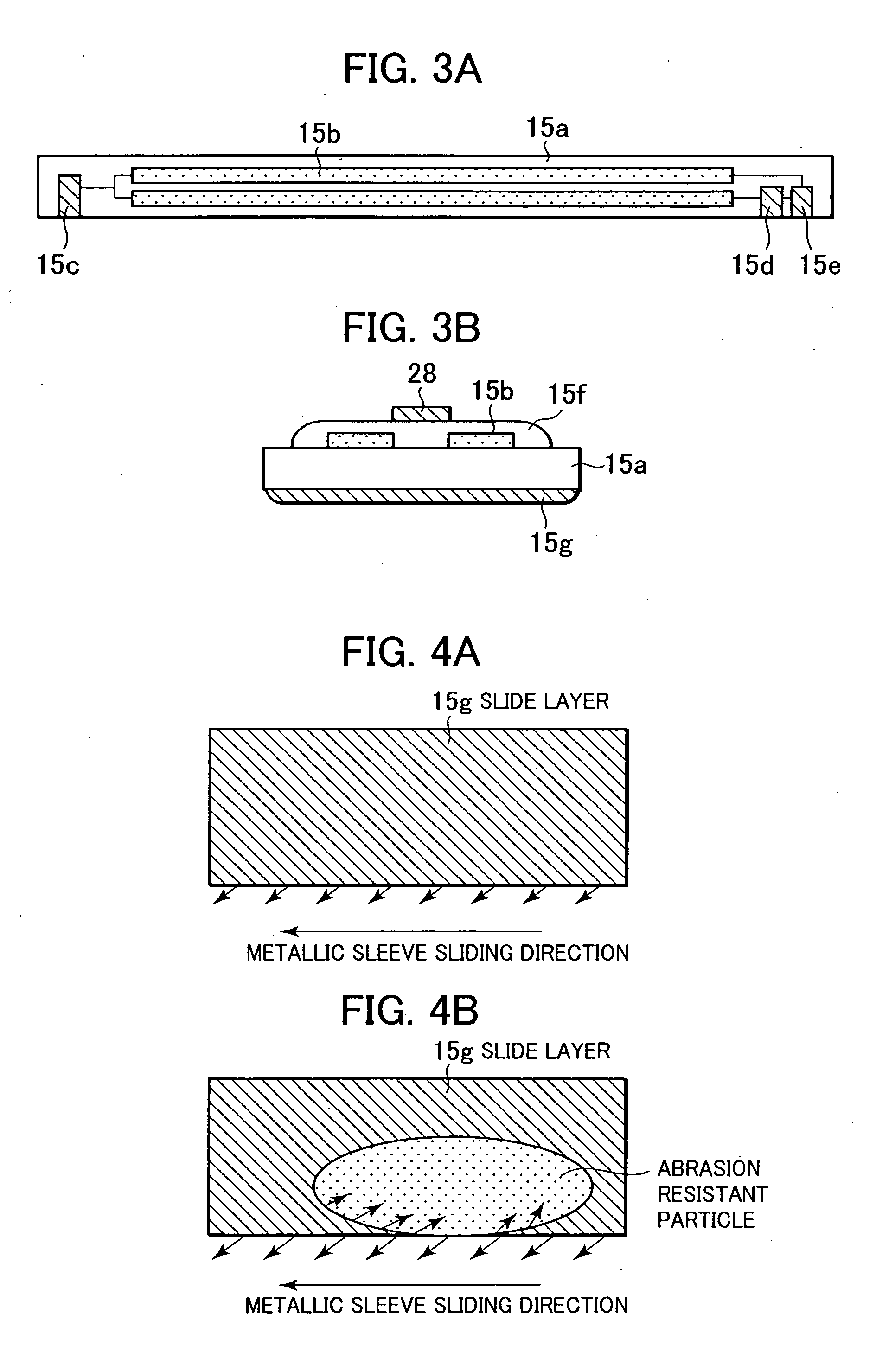
[0113]FIG. 7 is a detailed diagram showing the are of a heater according to the second embodiment. In this embodiment, a heater 15 is a narrow, plate-shaped ceramic heater of an obverse face heating type. Specifically a heat generating resistance layer 15b of the heater 15 is located on a heater substrate 15a near a fixing nip N, and a protective glass coat layer 15f is formed to protect the heat generating resistance layer 15b. Further, a slide layer 15g is overlaid to improve sliding relative to a flexible metallic sleeve 14.

[0114] Since a heat generation body 15b and the flexible metallic sleeve 14 should be completely insulate...


PUM

PropertyMeasurementUnit
thicknessaaaaaaaaaa
thicknessaaaaaaaaaa
mean sizeaaaaaaaaaa

Abstract

The present invention relates to an image thermal apparatus including a flexible metallic sleeve, the inner peripheral surface of which contacts a heater. In order to provide increased durability for the sliding face of the heater, an imide resin that contains silicon nitride elementary particles is used to coat the sliding face of the heater.

Description

BACKGROUND OF THE INVENTION [0001] 1. Field of the Invention [0002] The present invention relates to an image heating apparatus appropriate for use as a thermal fixing apparatus, mounted, for example, in a copier or a printer, and a heater employed for this apparatus. In particular, the present invention relates to an image heating apparatus having a flexible metallic sleeve and a heater employed for this apparatus. [0003] 2. Description of the Related Art [0004] Most conventional copiers and printers of an electrophotographic type adopt, as fixing means, a thermal roller fixing system, of a contact heating type, that provides satisfactory heating efficiency and safety, or a system whereby power is not supplied to a thermal fixing apparatus in the standby state and power consumption is as greatly reduced as possible; specifically, a film heating system of an energy saving type is one wherein a thin film is arranged between a heater and a pressure roller, and the thermal fixing of a ...

Claims


Application Information

Patent Timeline
Patent Type & Authority Applications(United States)
IPC IPC(8): G03G15/20H05B3/00
CPCG03G15/2064G03G15/2057
Inventor HASHIGUCHI, SHINJINIHONYANAGI, KOJIUEKAWA, EIJIHASEGAWA, HIROTO
Owner CANON KK
Why Eureka
Try Eureka