General purpose input board for a touch actuation

a technology of touch actuation and input board, which is applied in the direction of coding, pulse technique, instruments, etc., can solve the problems of thick construction, complicated and expensive, and limited input device selection

a technology of touch actuation and input board, which is applied in the direction of coding, pulse technique, instruments, etc., can solve the problems of thick construction, complicated and expensive, and limited input device selection

US20060060644A1Active Publication Date: 2006-03-23NOKIA TECHNOLOGLES OY

Image

  • General purpose input board for a touch actuation
  • General purpose input board for a touch actuation
  • General purpose input board for a touch actuation

Examples


Embodiment Construction

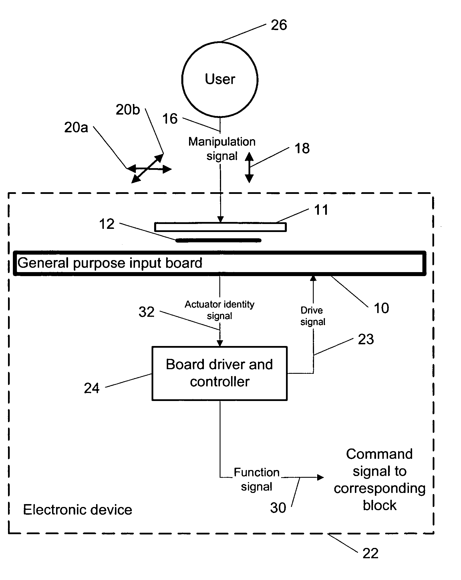
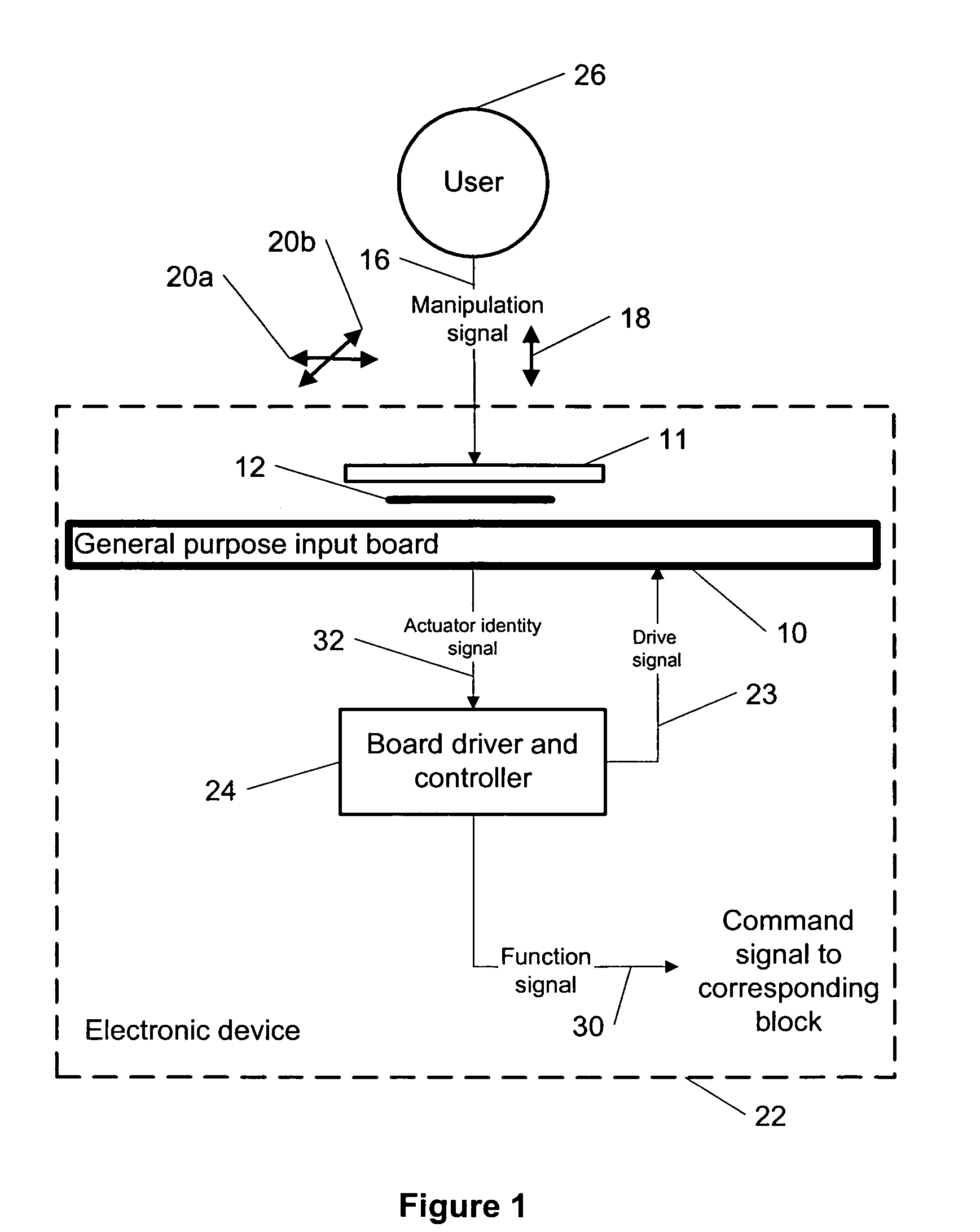
[0044] The present invention provides a new methodology for a touch actuation in an electronic device (e.g., a wireless portable device, a mobile communication device, a mobile phone, etc.) using a general purpose input board.

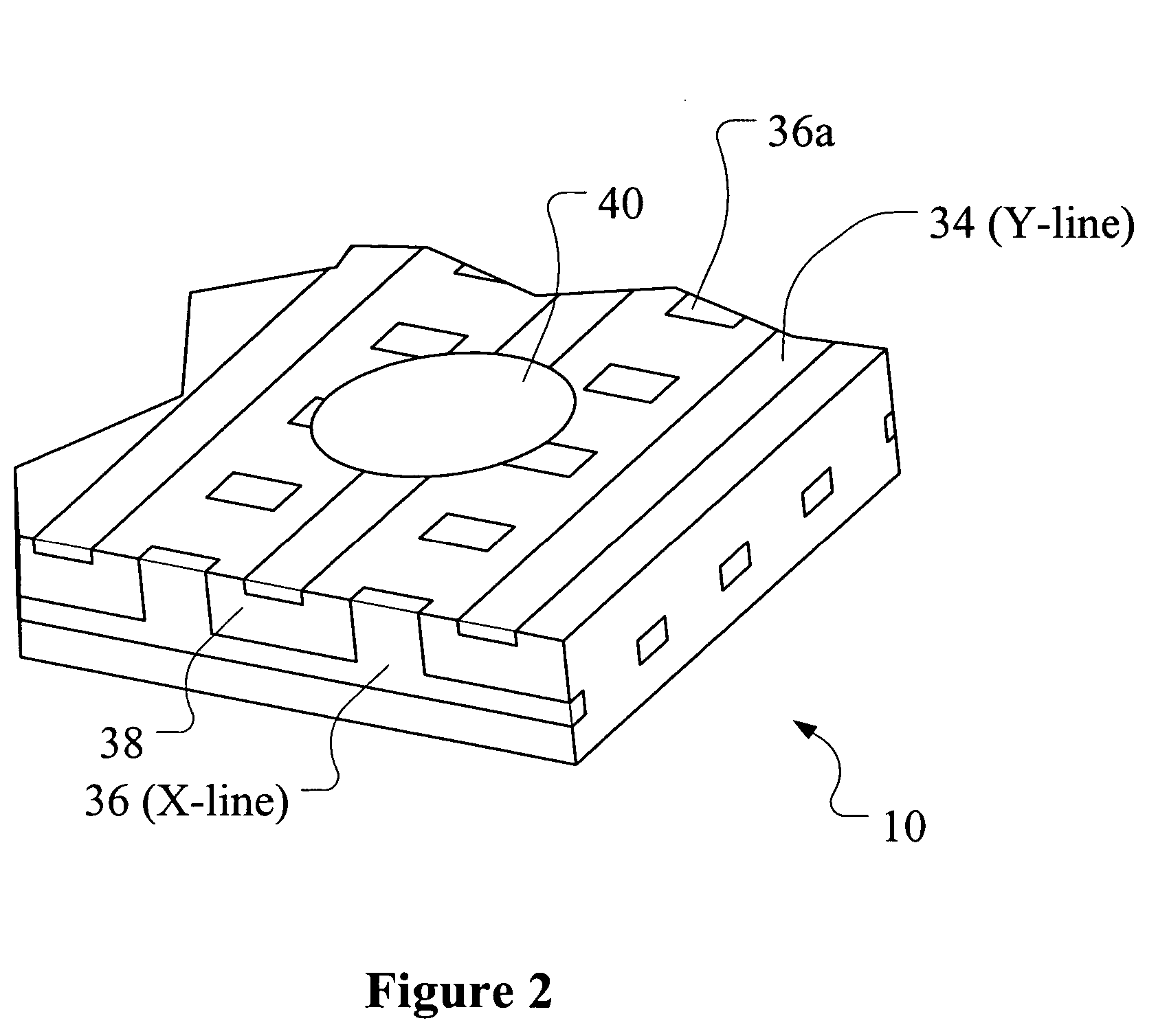
[0045] According to the present invention, the general purpose input board (or alternatively called an input board) comprises of a grating of conductors running in one direction (y-lines). Between these conductors there are contacts connected to a grating running in the perpendicular direction a layer below (x-lines). The grating layers are separated by an insulating layer. The input board can be manufactured using a wide variety of technologies, e.g., printable resistive, conductive and insulating materials. Various known methods (discussed below) can be used to read the position of any conductive actuator touching the input board. The input board can be used, e.g., as a configurable UI (user interface) board under a keymat. The input devices on the keymat ca...


PUM


Abstract

This invention describes a method for a touch actuation in an electronic device using a general purpose input board. The input board comprises of a grating of conductors running in one direction (y-lines). Between these conductors there are contacts connected to a grating running in the perpendicular direction a layer below (x-lines). The grating layers are separated by an insulating layer. The input board can be manufactured using a wide variety of technologies, e.g., printable resistive, conductive and insulating materials. Various known methods can be used to read the position of any conductive actuator touching the input board. The input board can be used as a configurable UI board under a keymat. The input devices on the keymat can be a key, a joystick, a touchpad top membrane, etc. and their configurations and positions can be freely varied on switchcovers. In addition, the actuators can be made force-sensitive by detecting a contact surface area.

Description

TECHNICAL FIELD [0001] This invention generally relates to electronic touch-devices and more specifically to a touch actuation in an electronic device using a general purpose input board. BACKGROUND ART [0002] Presently, switchcovers of a given phone (e.g., a mobile phone) type mostly differ in their appearance whereas a number, positioning and a type of input devices is similar for most of the switchcovers due to construction of a UI (user interface) board. Typically, the input board contains contact pads at positions corresponding to keys on a keymat. Each pad is essentially the size of the corresponding key. As the key is depressed, its conductive lower surface short-circuits the two wires on the contact pad. The pad can also utilize capacitive or force sensing technology for detecting a keypress. [0003] The reason for using metal or rubber domes as switches is that they give tactile feedback of a key activation to a user. It is also possible to use so called membrane switches, w...

Claims


Application Information

Patent Timeline
23 Mar 2006
Publication
US20060060644A1
IPC
G06C7/02
CPC
G06F3/0202; G06F3/0205; G06F3/03547; H01H13/702; H01H2239/012; H01H2221/002; H01H2221/012; H01H2231/022
Inventors
PIHLAJA, PEKKA