Ultrasonic cement scanner

a scanner and ultrasonic technology, applied in seismology, instruments, constructions, etc., can solve the problems of internal and external corrosion, wear of the casing from within, mechanical wear, etc., and achieve the effect of minimizing the requirements for telemetry band width

Inactive Publication Date: 2006-03-30
PRECISION DRILLING TECH SERVICES GROUP +1
View PDF32 Cites 64 Cited by
  • Summary
  • Abstract
  • Description
  • Claims
  • Application Information

AI Technical Summary

Benefits of technology

[0011] Parameters of interest can be computed within the borehole assembly and telemetered to the surface thereby minimizin

Problems solved by technology

Corrosion can occur both inside and outside of the casing.
Mechanical wear from pump rods and the like can wear the casing from within.
Any type of casing wear can affect the casing's ability to provide mechanical strength for the borehole.
If the cement is not properly bonded to the outer surface of the casing, hydraulic isolation is compromised.
If the cement does not completely fill the casing-cement annulus, hydraulic isolation is also compromised.
Furthermore, if casing corrosion occurs on

Method used


Image

  • Ultrasonic cement scanner
  • Ultrasonic cement scanner
  • Ultrasonic cement scanner

Examples


Embodiment Construction

Overview of the System

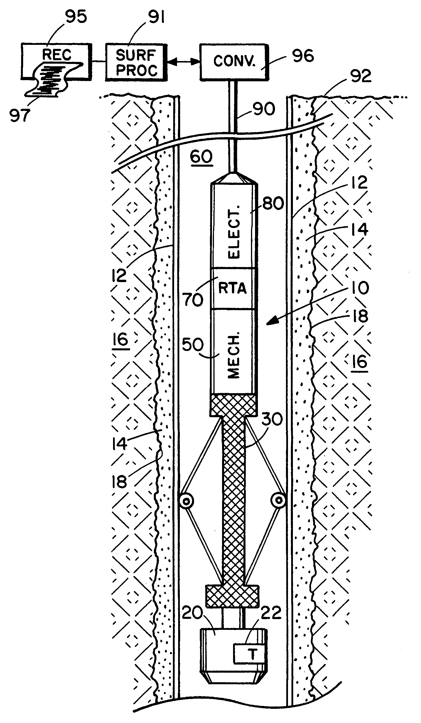
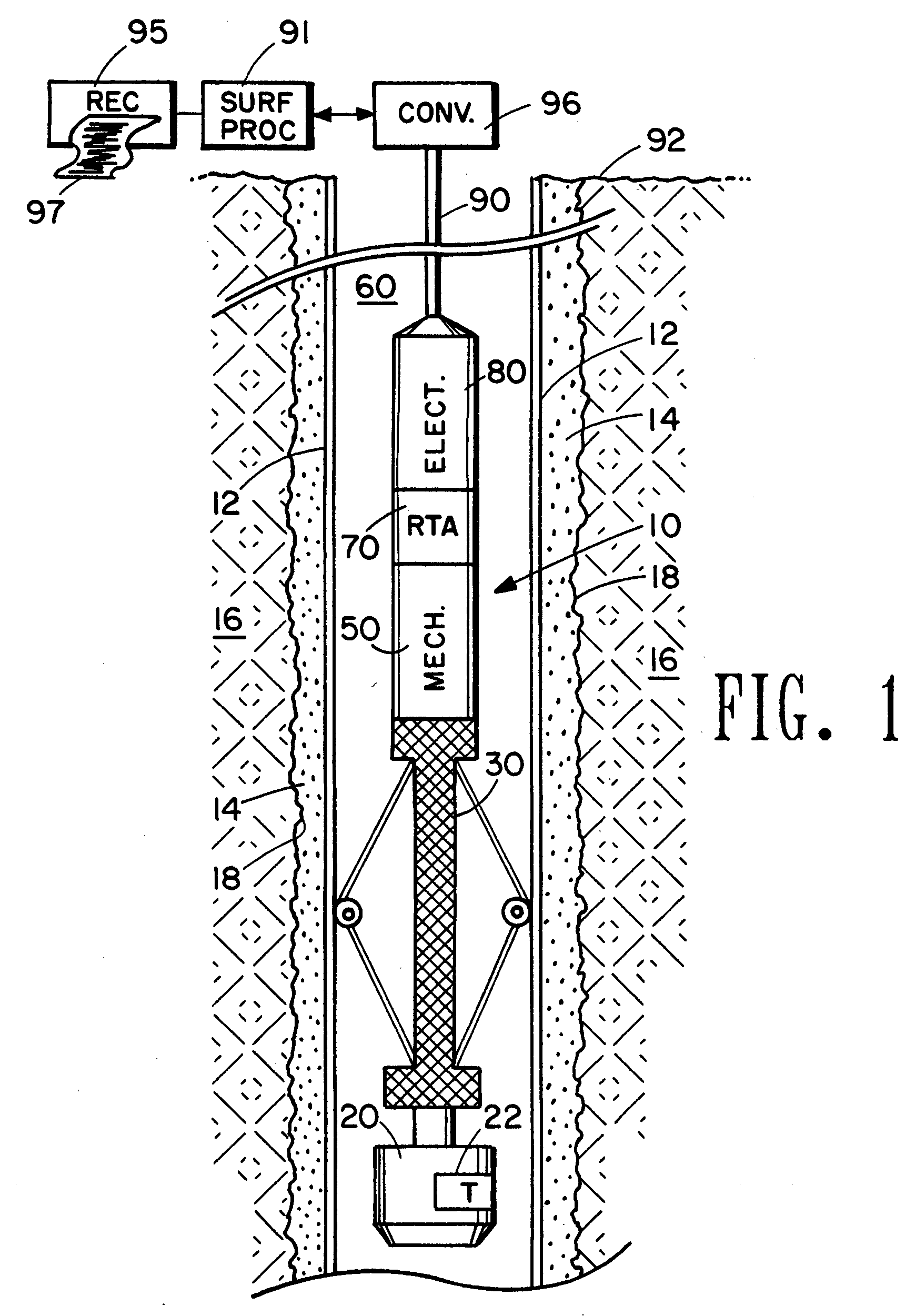
[0022]FIG. 1 illustrates the major elements of the Ultrasonic Cement Scanner logging system operating in a well borehole environment. The downhole apparatus or “tool”, identified as a whole by the numeral 10, is suspended at a down hole end of a data conduit 90 in a well borehole defined by walls 18 and penetrating earth formation 16. The borehole is cased with a tubular casing 12, and the annulus defined by the borehole wall 18 and the outer surface of the casing 12 is filled with a grout 14 such as cement. The casing is filled with a fluid 60.

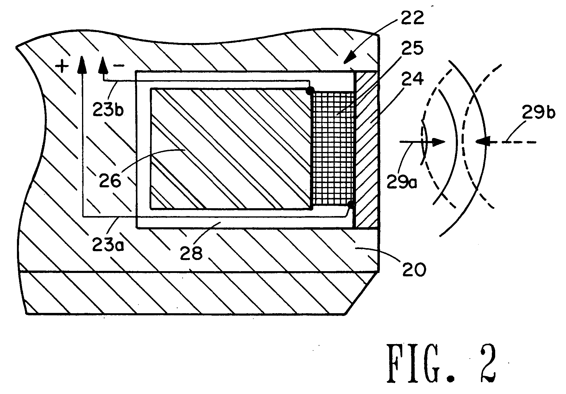
[0023] Again referring to FIG. 1, the lower end of the tool 10 is terminated by a scanning head 20 comprising an ultrasonic scanning transducer 22 of known frequency response. The scanning head is rotated about the major axis of the tool 10, and the scanning transducer 22 is activated or “fired” in sequential bursts as the scanning head 20 is rotated. The scanning transducer 22 is disposed such that emitted acoustic e...


PUM


Abstract

An acoustic borehole logging system for parameters of a well borehole environs. Full wave acoustic response of a scanning transducer is used to measure parameters indicative of condition of a tubular lining the well borehole, the bonding of the tubular to material filling an annulus formed by the outside surface of the tubular and the wall of the borehole, the distribution of the material filling the annulus, and thickness of the tubular. A reference transducer is used to correct measured parameters for variations in acoustic impedance of fluid filling the borehole, and for systematic variations in the response of the scanning transducer. Corrections are made in real time. The downhole tool portion of the logging system is operated essentially centralized in the borehole using a centralizer that can be adjusted for operation in a wide range of borehole sizes.

Description

[0001] This invention is directed toward a borehole logging system for the measure of properties and conditions of a well borehole environs. More particularly, the invention is directed toward an acoustic logging system for measuring and mapping physical condition of a tubular lining the well borehole, the bonding of the tubular to material filling an annulus formed by the outside surface of the tubular and the wall of the borehole, and the distribution of the material within the annulus. BACKGROUND OF THE INVENTION [0002] Well boreholes are typically drilled in earth formations to produce fluids from one or more of the penetrated formations. The fluids include water, and hydrocarbons such as oil and gas. Well boreholes are also drilled in earth formations to dispose waste fluids in selected formations penetrated by the borehole. The boreholes are typically lined with tubular commonly referred to as casing. Casing is typically steel, although other metals and composites such as fibe...

Claims


Application Information

Patent Timeline
IPC IPC(8): G01V1/40
CPCG01V1/44E21B47/0005E21B47/005
Inventor BLANKINSHIP, THOMAS J.ROBERTS, EDWIN K.TELLO, LUCIO N.
Owner PRECISION DRILLING TECH SERVICES GROUP
Why Eureka
Try Eureka