Method and apparatus for logging foam cement in cased boreholes

a technology of foam cement and cased boreholes, which is applied in seismology, instruments, constructions, etc., can solve the problems of difficult distinguishing foam cement from liquid or gas well fluid, affecting the accuracy of telemetry, and compromising hydraulic isolation, so as to minimize the width requirements of the telemetry band

Inactive Publication Date: 2009-04-02
WEATHERFORD TECH HLDG LLC
View PDF3 Cites 25 Cited by
  • Summary
  • Abstract
  • Description
  • Claims
  • Application Information

AI Technical Summary

Benefits of technology

[0010]Mathematical computations can optionally be performed in a processor within the ultrasonic scanning tool and telemetered to the surface thereby minimizing telemetry band width requirements.

Problems solved by technology

If the grouting material such as conventional or foam cement does not fill the casing-borehole annulus or is not properly bonded to the casing, hydraulic isolation is compromised.
Distinguishing foam cement from liquid or gas well fluid is difficult using only acoustic impedance measurements from cement evaluation tools, including ultrasonic radial scanning type tools.
This lack of impedance contrast often results in an indication of voids within a foam cement sheath behind casing, or that casing is “free” when it may be well bonded to foam cement.

Method used


Image

  • Method and apparatus for logging foam cement in cased boreholes
  • Method and apparatus for logging foam cement in cased boreholes
  • Method and apparatus for logging foam cement in cased boreholes

Examples


examples presented

[0049 below that illustrate fluid and foam cement effects on the acoustic impedance measurement and on the resulting final impedance maps.

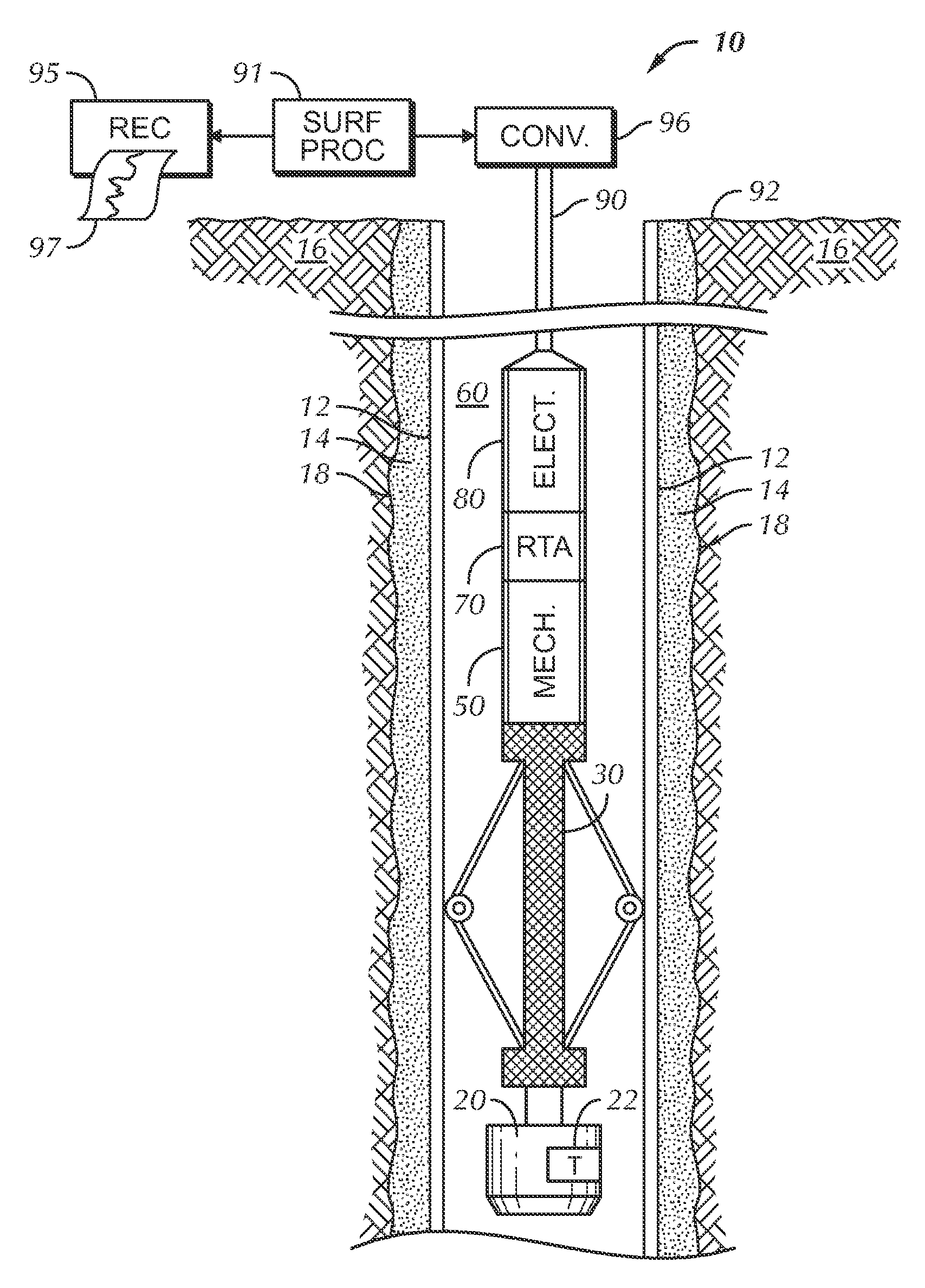
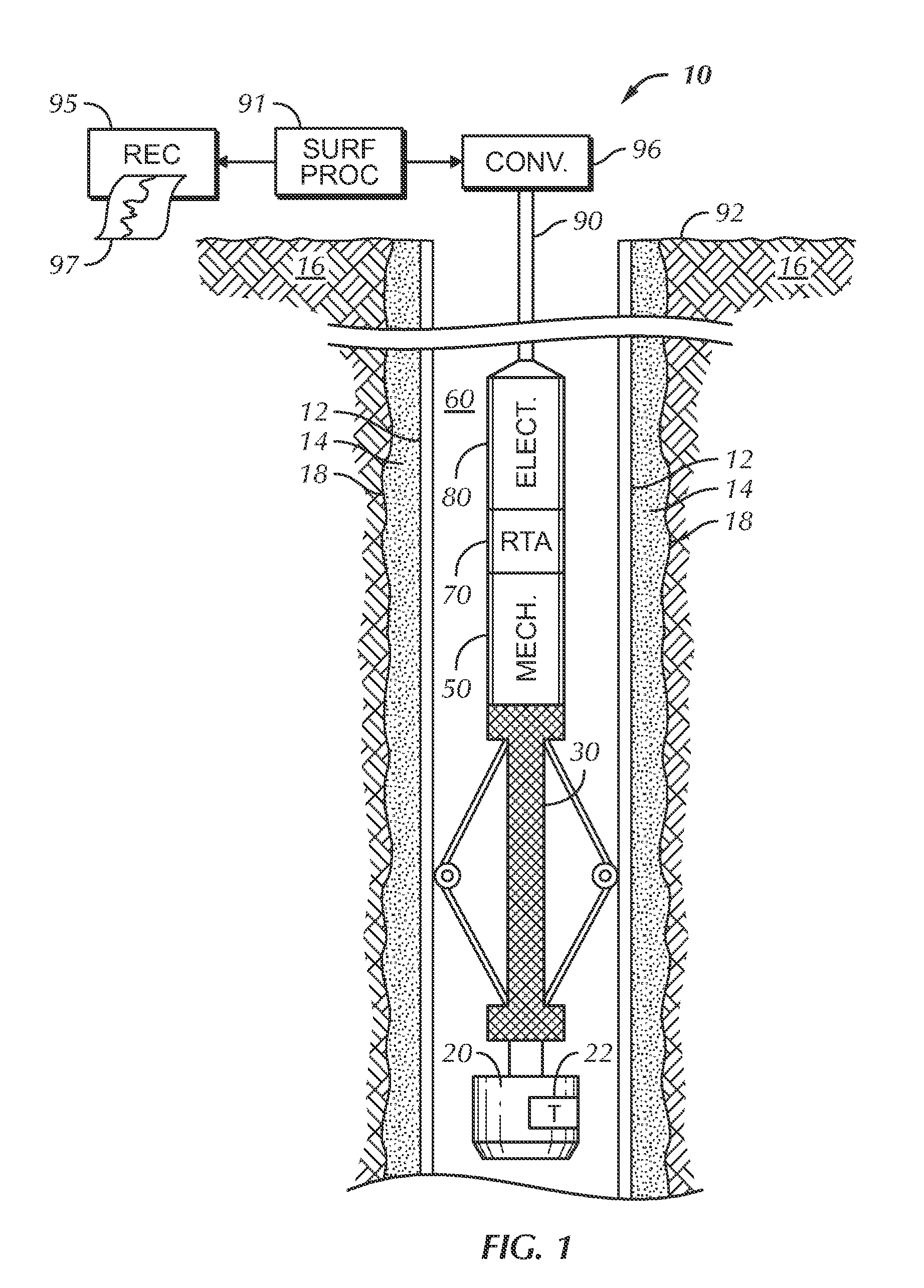
[0050]FIG. 3 is an impedance map and a group of eight related impedance logs illustrating response of the ultrasonic cement scanner logging system to a situation in which well fluid fills the casing-borehole annulus. Recall that the rotating transducer 22 preferably fires 72 times per azimuthal rotation within the borehole. Groups or “tracks” of curves 124, 126, 128, 130, 132, 134 and 136 comprise “traces” each represent nine logs of acoustic impedance Zi(x) computed from transducer responses in azimuthal arc segments 0-45 degrees, 46-90 degrees, 91-135 degrees, 136-180 degrees, 181-225 degrees, 226-270 degrees, 271-315 degrees, and 316-360 degrees, respectively. The vertical axis represents depth x in the borehole. Note the small variation in individual traces of Zi(x) over depth intervals of a few feet, except for excursions 140 at casing collar...


PUM


Abstract

An acoustic logging system that measures distribution of foam cement and other material in a casing-borehole annulus. The distribution is preferably displayed as map. A borehole tool utilizes at least one acoustic transducer with a known frequency response and mounted on a rotating scanning head that is pointed essentially perpendicular to the borehole wall. The response of the transducer is used to measure an original impedance map of material within the borehole-casing annulus. A fast Fourier transform is used to generate a FFT map from the data comprising the original impedance map. The original impedance map is then combined with the FFT map using logic rules to obtain a final impedance map that is indicative of material within the casing-borehole annulus.

Description

[0001]This invention is directed toward a borehole logging system for the measure of properties and conditions of a well borehole environs. More particularly, the invention is directed toward an acoustic logging system for identifying and mapping distribution of material filling an annulus formed by the outside surface of the tubular and the wall of the borehole. This material includes foam cement as well as conventional cement and liquids.BACKGROUND OF THE INVENTION[0002]Well boreholes are typically drilled in earth formations to produce fluids from one or more of the penetrated formations. The fluids include water, and hydrocarbons such as oil and gas. Well boreholes are also drilled in earth formations to dispose waste fluids in selected formations penetrated by the borehole.[0003]The boreholes are typically lined with tubulars commonly referred to as casing. Casing is typically steel, although other metals and composites such as fiberglass can be used. The outer surface of the c...

Claims


Application Information

Patent Timeline
Patent Type & Authority Applications(United States)
IPC IPC(8): G01V1/40
CPCG01V1/44E21B47/0005E21B47/005
Inventor TELLO, LUCIO N.MOLDER, SARAH D.
Owner WEATHERFORD TECH HLDG LLC
Why Eureka
Try Eureka