Method and device for microsurgical intermuscular spinal surgery

a technology of intermuscular spinal surgery and microsurgical operation, which is applied in the field of microsurgical intermuscular spinal surgery, can solve the problems of inability to specifically the ability to frequently compromise the posterior lumbar fusion, and the inability to precisely retract the requisite structur

Inactive Publication Date: 2007-01-23
RITLAND STEPHEN
View PDF264 Cites 186 Cited by
  • Summary
  • Abstract
  • Description
  • Claims
  • Application Information

AI Technical Summary

Benefits of technology

[0007]One method of retraction is to use a muscle splitting or intermuscular approach to access the spine for fixation and for interbody fusion or dynamic fixation. An angled retractor offers the advantage of being able to be manipulated by a surgeon to engage the implant construct and retract the muscles medially to provide a window of access medial to the implant construct with secure fixation against the implant. This device enables a surgeon to access the pedicle for screw placement.
[0008]Preferred embodiments of the present invention allow a surgeon to minimize the exposure needed for surgery, thereby minimizing the necessary retraction, and also allows the device to be used with a guide wire or drill with a minimum approach. The retractors of the present invention can be made in a right and left configuration, and the blade is typically used in lengths ranging from about 25 to 90 mm from its proximal end to its distal end. In addition, the blade is preferably angled relative to the attached handle at an angle of about 90 degrees or greater, and more preferably, at an angle of about 115 degrees to correspond to the typically needed trajectory for screw placement into the lumbar spine. In addition, a separate aspect of the present invention is a blade having a width of about 12 to 16 mm to provide an appropriate window for a typical polyaxial screw and with one or a plurality of points to engage and stabilize the retractor.
[0009]Thus, in one embodiment of the present invention, a tissue retractor for use in surgery of a spine is provided, wherein the retractor includes a handle and a blade connected to the handle at an intersection. Preferably, the handle forms an angle with the blade of between about 90 and 135 degrees, and more preferably, the handle forms an angle with the blade of about 115 degrees. The blade includes a first face and a second face positioned transverse to the first face, and more preferably, the first face is substantially perpendicular to the second face with a quarter-rounded bend interconnecting the first face to the second face. In accordance with embodiments of the present invention, the second face has an upper proximal edge spaced apart from the intersection, and the second face also preferably has a variable width, with a first larger width at a location positioned proximally of a second narrower width at the distal end of the second face. In accordance with embodiments of the present invention, the distal end of the second face includes at least one co-planar forward projecting tooth for laterally engaging an articular complex of a vertebra of the spine. In addition, the first and second faces of the blade preferably include a partially rounded tip at the distal end of the blade. The first face optionally includes a terminal indentation or a distal tooth at the distal end of the blade, wherein the terminal indentation or distal tooth are adapted to engage a transverse process of the vertebra. The retractor optionally further includes a third face located transverse to the first face and opposite the second face, wherein the first face is substantially perpendicular to the third face with a quarter-rounded bend interconnecting the first face to the third face. In accordance with embodiments of the present invention, the first, second and third faces preferably form a U-shape, with the third face substantially parallel to the second face. Similar to the second face, the third face preferably includes at least one co-planar forward projecting tooth, and more preferably, a plurality of co-planar forward projecting teeth. In one example of this embodiment, the third face further includes an upper proximal edge located distally of the upper proximal edge of the second face. The first face of the blade may also have a variable width, preferably including a first larger width at a location positioned proximally of a second narrower width at a distal end of the first face. The retractor preferably includes a partially rounded smooth outer blade surface that allows tissue to easily slide along the outer surface of the retractor as the retractor is inserted or withdrawn from a surgical site. Finally, the retractor may optionally include a tool groove along its first face.
[0010]In accordance with embodiments of the present invention, a retractor is provide wherein the retractor includes a handle and a blade connected to the handle, the blade including a first face and a second face positioned substantially perpendicular to the first face. In accordance with embodiments of the present invention, the second face includes at least one tooth for laterally engaging an articular process of a vertebra of the spine. The first face has a tapered width with a first larger width at a location positioned proximally of a second narrower width at a distal end of the first face, and the second face also has a tapered width with a larger width positioned proximally of a narrower width at a distal end of the second face. The retractor can be made in a left or a right hand configuration to accommodate approaching the spine from either side. When used in lumbar surgery, the blade preferably has a length between about 25 to 90 and the handle forms an angle with the blade of between about 90 and 135 degrees, and more preferably, the handle forms an angle with the blade of about 115 degrees. The blade preferably includes a curved transition between the first face and the second face. The curved transition can comprise a constant radius curve, or it can comprise a tapered conic section consistent with the taper of the first face and the taper of the second face. The retractor optionally includes a third face located transverse to the first face, wherein the first face is substantially perpendicular to the third face, and wherein the first, second, and third faces form a U-shaped interior surface. Similar to the second face, the third face preferably includes at least one co-planar forward projecting tooth, and more preferably, a plurality of co-planar forward projecting teeth. The retractor also preferably includes a partially rounded smooth outer blade surface that allows tissue to easily slide along the outer surface of the retractor as the retractor is inserted into or removed from a surgical site. Finally, the retractor may optionally include a tool groove along its first face.

Problems solved by technology

Results of posterior lumbar fusion have frequently been compromised by residuals from muscular and neurovascular disruption accompanying arthrodesis.
Present techniques of lumbar arthrodesis including instrumentation and interbody fusion provide a reasonable expectation of fusion with surgery; however, outcomes remain limited by pain and adjacent segment failure.
To the extent this results from fusion it may be unavoidable.
For heretofore available retractors, more retraction than necessary was performed and the ability to specifically retract requisite structures was impaired.
Specifically, the small muscles traversing the transverse process were more difficult to engage and may have been damaged by excess retraction.
Additionally, a larger retractor was more difficult to place in the intermuscular plane opened for access.

Method used


Image

  • Method and device for microsurgical intermuscular spinal surgery
  • Method and device for microsurgical intermuscular spinal surgery
  • Method and device for microsurgical intermuscular spinal surgery

Examples


Embodiment Construction

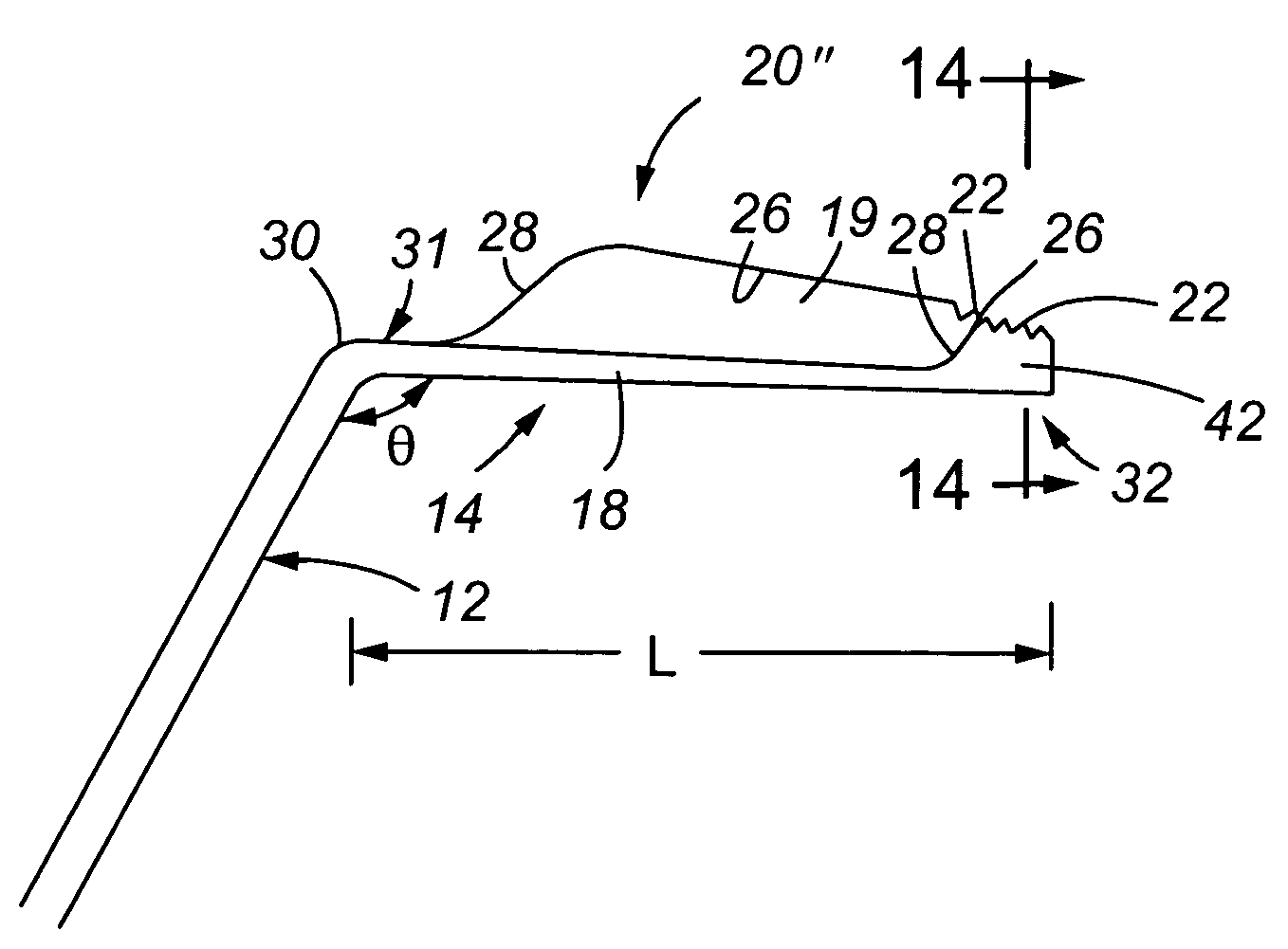
[0033]The present invention is directed to a device and a method for performing an instrumented lumbar interbody fusion or dynamic fixation utilizing a minimally invasive approach. The device used by the surgeon to perform the minimally invasive approach is a retractor, wherein the retractor has a number of structural features as set out below that enable the surgeon to use the retractor to perform a minimally invasive surgical procedure.

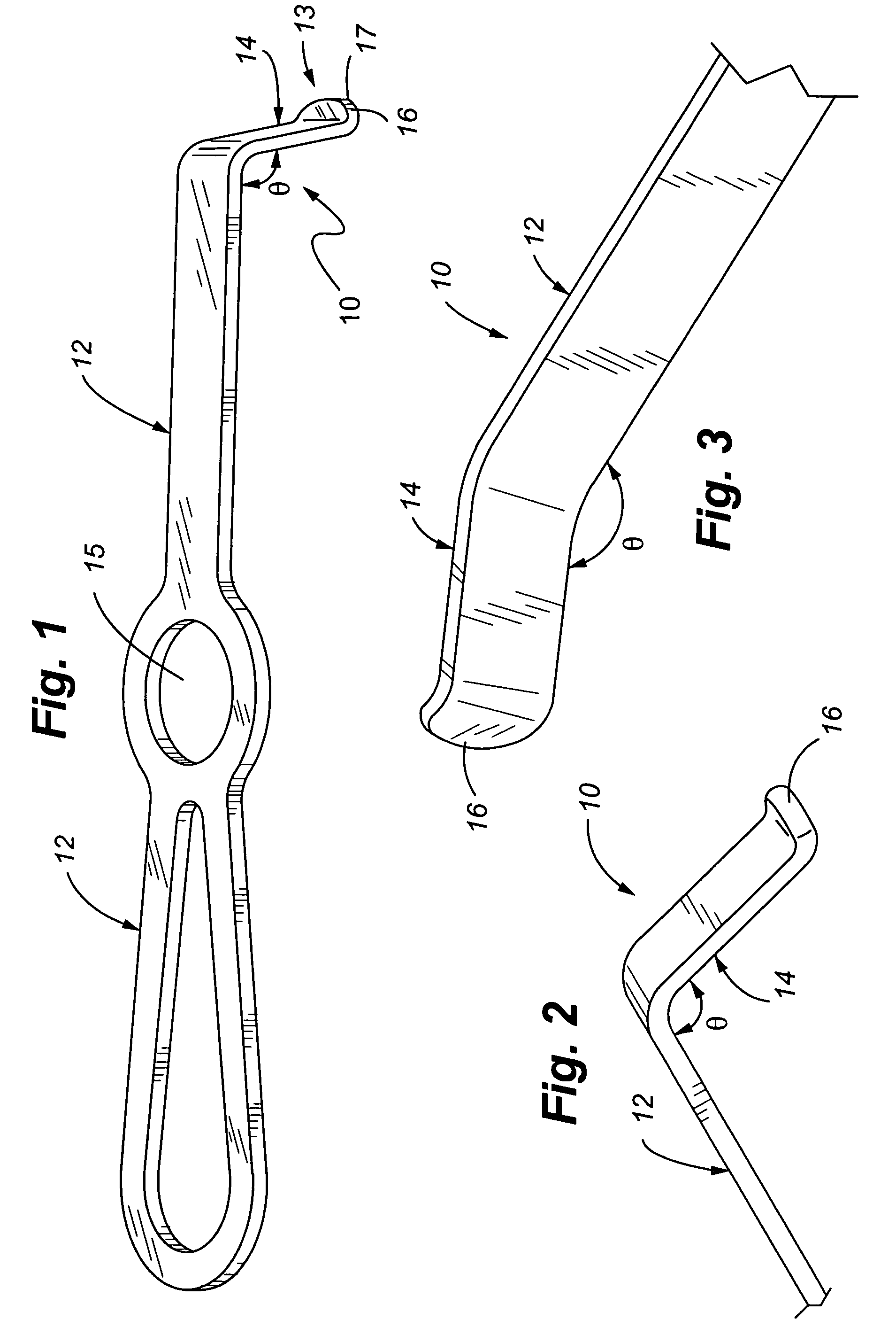
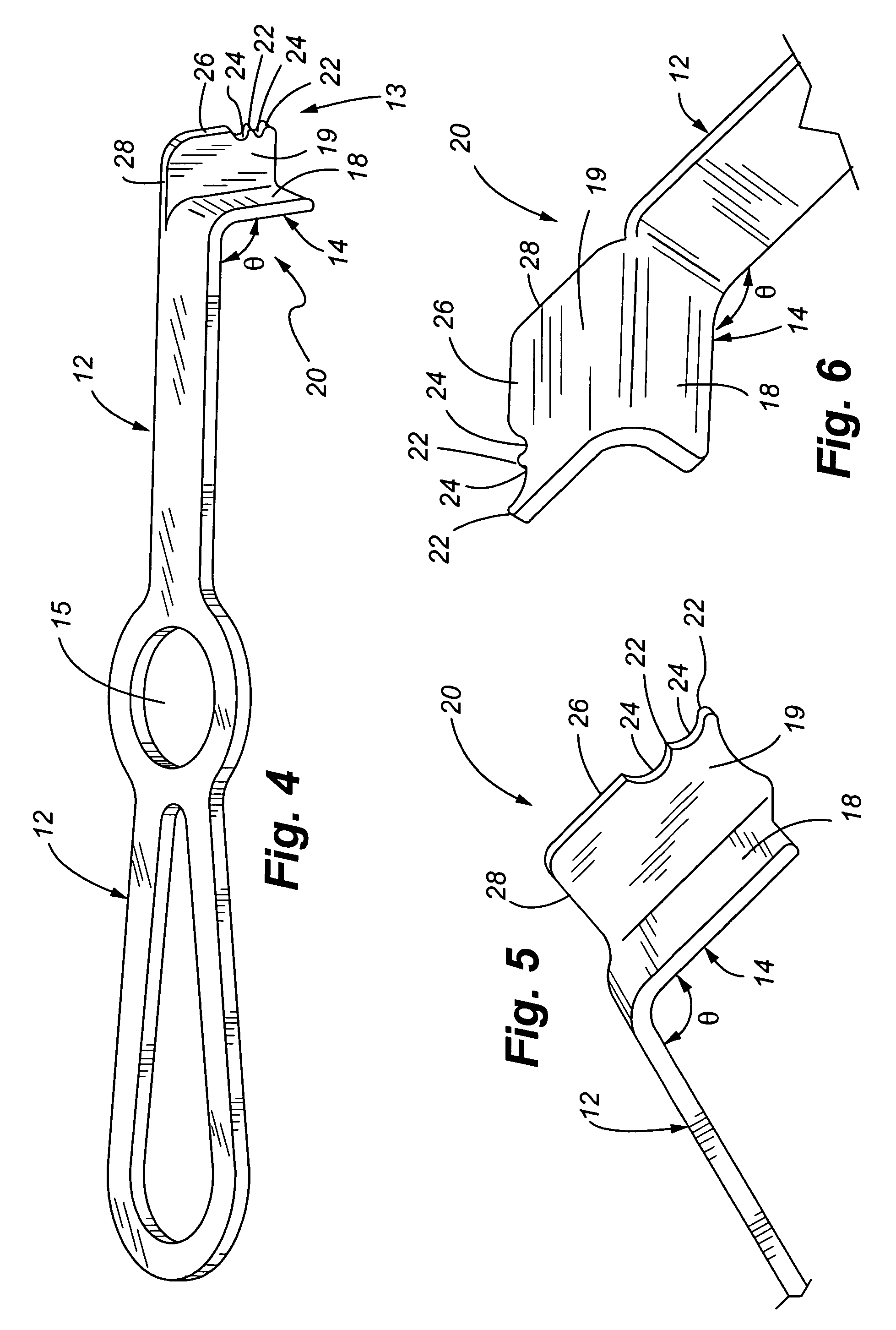
[0034]Referring now to FIGS. 1–3, a first embodiment of the present invention is illustrated and is generally directed to the use of a tissue retractor 10 for use in lumbar arthrodesis or dynamic fixation. For the first embodiment, retractor 10 includes a handle 12 at one end, and a retractor blade 14 at a second end. The handle 12 allows a surgeon to hold and manipulate the retractor 10 and thereby manipulate a functional tip 13 of the retractor 10 to work in the intermuscular plane, engage the articular complex, and provide working access for plac...


PUM


Abstract

A retractor is provided for performing spinal surgery with a minimal approach, and which spares the lumbar muscles from surgical disruption. A preferred embodiment includes a blade having first and second faces wherein the faces are positioned substantially transverse to one another, and wherein at least one of the faces has a tapered width. Alternatively, both the first and second faces are tapered. Additionally, a third face positioned transverse to the first face and substantially parallel to the third face may be incorporated into the retractor. The second face also preferably includes at least one tooth, and more preferably, a plurality of teeth at its distal end for laterally engaging an articular process of a vertebra of the spine.

Description

CROSS REFERENCE TO RELATED APPLICATIONS[0001]This application is a continuation-in-part of prior U.S. patent application Ser. No. 10 / 745,068 filed Dec. 22, 2003, pending which is a continuation of U.S. patent application Ser. No. 09 / 969,138 filed on Oct. 1, 2001 (now U.S. Pat. No. 6,692,434 which issued Feb. 17, 2004), which claimed the benefit of U.S. Provisional Patent Application No. 60 / 236,584 filed on Sep. 29, 2000; in addition, the present application claims the benefit of U.S. Provisional Application No. 60 / 556,967 filed Mar. 26, 2004. The entire disclosures of these applications are considered to be part of the disclosure of the present application and are hereby incorporated by reference in their entirety.FIELD OF THE INVENTION[0002]The present invention is directed to a method and device for microsurgical intermuscular spinal surgery.BACKGROUND OF THE INVENTION[0003]In performing surgery on the spine, including the lumbar vertebrae, retractors are used to maintain necessar...

Claims


Application Information

Patent Timeline
Patent Type & Authority Patents(United States)
IPC IPC(8): A61B17/02A61B1/32A61B17/32
CPCA61B17/02A61B17/025A61B2017/0256A61B17/3211
Inventor RITLAND, STEPHEN
Owner RITLAND STEPHEN
Why Eureka
Try Eureka