Head gimbal assembly with flying height controller, disk drive unit using the same, and flying height adjusting method and system thereof

a technology of flying height controller and assembly, which is applied in the direction of circuit inspection/integration, instruments, final product manufacturing, etc., can solve the problems of reducing flying height, not increasing flying height, and slider damage or disk damage, and achieve good flying height adjustment capability

Inactive Publication Date: 2006-04-20
SAE MAGNETICS (HK) LTD
View PDF9 Cites 64 Cited by
  • Summary
  • Abstract
  • Description
  • Claims
  • Application Information

AI Technical Summary

Benefits of technology

[0007] A main feature of the present invention is to provide a HGA and a disk drive unit having a good flying height adjustment capability, and a method for flying height control using the HGA and disk drive.

Problems solved by technology

That is, if the flying height is too high, it will affect the slider reading data from or writing data to the disk; on the contrary, if the flying height is too low, the shock of the slider may scratch the disk so as to cause the damage of the slider and / or the disk.
However, the flying height adjustment capability of the flying height controller 130 have a limitation, that is, it can only reduce the flying height, but can not increase the flying height.
Also, since the flying height controller 130 is far away from the slider, its adjustment accuracy is rather limited.
Finally, because the flying height controller 130 has a complex structure, so it is rather costly and takes much time to manufacture such a flying height controller 130.

Method used


Image

  • Head gimbal assembly with flying height controller, disk drive unit using the same, and flying height adjusting method and system thereof
  • Head gimbal assembly with flying height controller, disk drive unit using the same, and flying height adjusting method and system thereof
  • Head gimbal assembly with flying height controller, disk drive unit using the same, and flying height adjusting method and system thereof

Examples


first embodiment

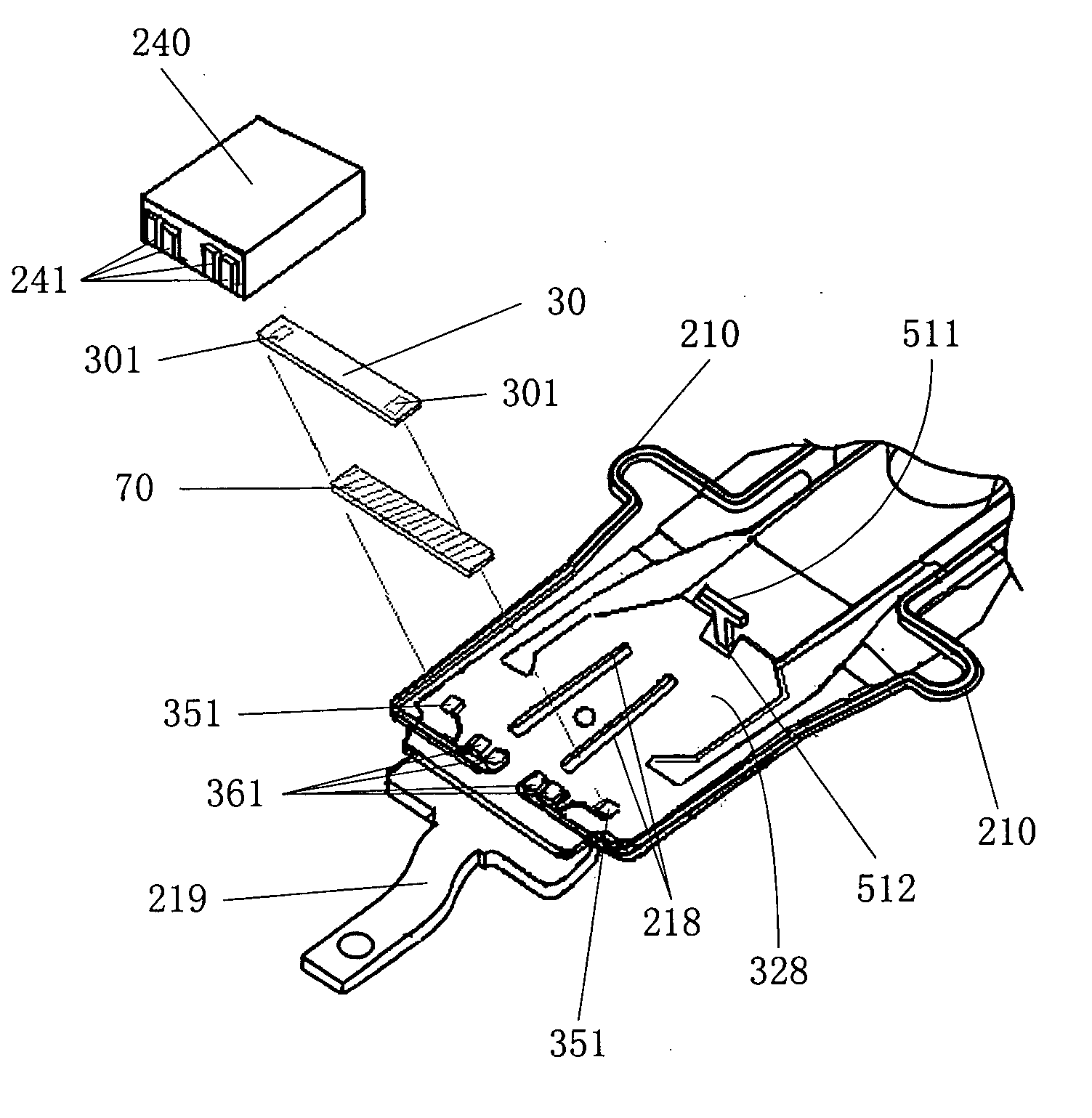
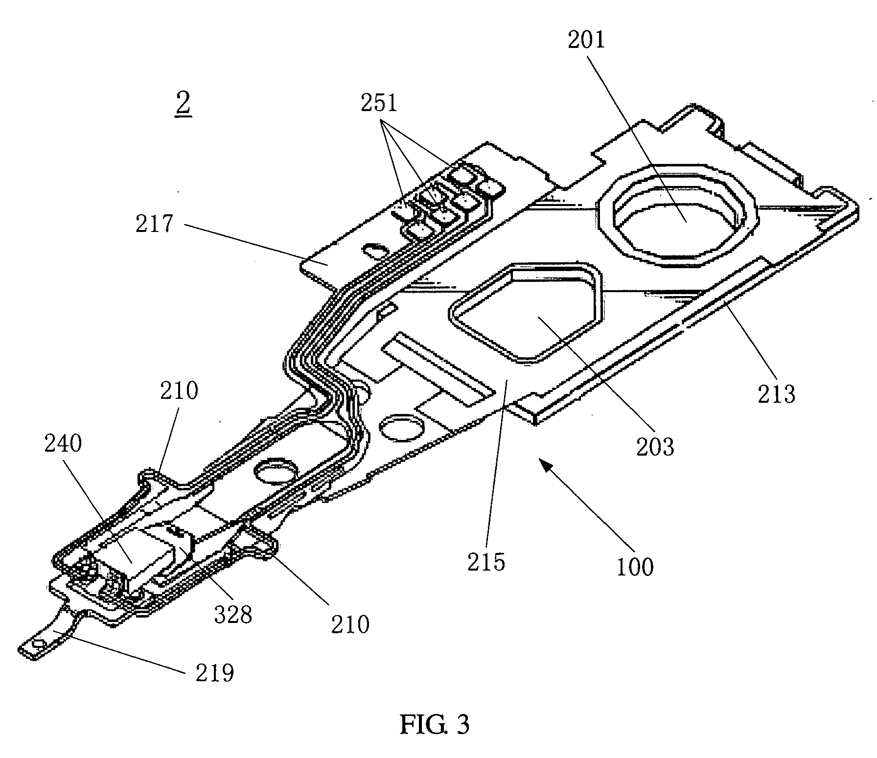
[0038] Referring to FIG. 3, according to the present invention, a head gimbal assembly (HGA) 2 comprises a slider 240, a flying height adjuster and a suspension 100.

[0039] Referring to FIGS. 3 and 4, the slider 240 is provided with a plurality of electrical pads 241 on one side thereof. The flying height adjuster is actually a piezoelectric (PZT) piece 30 which has two electrical pads 301 on both sides thereof. The suspension 100 comprises a load beam 219, a flexure 217, a hinge 215 and a base plate 213. As an embodiment, the flexure 217 is coupled with the hinge 215, the load beam 219 and the base plate 213 by laser welding. In the embodiment, the load beam 219 has one dimple 329 (see FIG. 6) and one limiter 511 provided thereon. Each of the hinge 215 and the base plate 213 forms two holes 201 and 203 therein. The hole 201 is used for swaging the HGA 2 and the drive arm (not shown), and the hole 203 is used to reduce the weight of the suspension 100. Also referring to FIGS. 3 and 4...

fourth embodiment

[0051] In the HGA of the present invention, referring to FIGS. 19-21, the ceramic U-shaped frame 801 with two PZT pieces 803 may be replaced by a metal support base 860 and a piezoelectric (PZT) unit 850. The PZT unit 850 comprises two thin film PZT pieces 853 (also can be ceramic PZT pieces) and a plurality of electrical pads (not shown) on one side thereof. The support base 860 comprises a base 861, a leading beam 862, and a moving plate 865 with two side beams 863 in its both sides. In an embodiment of the invention, the width of the leading beam 862 is narrower than that of the moving plate 865. The PZT unit 850 physically couples with the support base 860 by traditional method, such as adhesive bonding. The suspension tongue 328 of the suspension 100 is separated into two parts, one is moving part 703″ and the other is steady part 702″. Two narrow slots 218′ are formed in the steady part 702″ for reducing the stiffness of the suspension tongue 328, and the dimple 329 (see FIG. ...


PUM

PropertyMeasurementUnit
thicknessaaaaaaaaaa
thicknessaaaaaaaaaa
thicknessaaaaaaaaaa

Abstract

A HGA comprises a slider, a suspension to load the slider, a flying height controller for controlling flying height of the slider; and a flexible cable to be electrically connected with the slider and the flying height controller. In the present invention, the flying height controller comprises at least one piezoelectric piece disposed between the slider and the suspension. The HGA further comprises ACF to connect the flying height controller with the suspension and the flexible cable. The invention also discloses a disk drive unit with the HGA, a method for flying height control with the HGA, and a system for controlling flying height.

Description

FIELD OF THE INVENTION [0001] The present invention relates to head gimbal assemblies and disk drive units having a good flying height adjustment capability, and also relates to a method and system of adjusting flying height. BACKGROUND OF THE INVENTION [0002] A data storage system, such as disk drive, generally includes one or more magnetic disks which are rotated by a spindle motor at a constant speed, and one or more information storage heads (generally called “sliders”) flying on the magnetic disk(s) to write data information to or read data information from the magnetic disks. The slider includes a bearing surface, such as an air bearing surface (ABS), which faces the disk surface. When the disk rotates, the air pressure between the disk and the ABS increases, which creates a hydrodynamic lifting force that causes the slider to lift and fly above the disk surface. [0003] As is well known in the art, each of the sliders is mounted on a suspension which is supported by a drive ar...

Claims


Application Information

Patent Timeline
Patent Type & Authority Applications(United States)
IPC IPC(8): G11B21/02G11B5/48G11B5/54
CPCG11B5/4853G11B5/5552G11B5/6005H05K1/0268H05K3/303H05K3/3442H05K2201/10083H05K2201/10727H05K2203/306G11B5/483Y02P70/50
Inventor YAO, MINGGAOSHIRAISHI, MASASHI
Owner SAE MAGNETICS (HK) LTD
Why Eureka
Try Eureka