Pedal system

Inactive Publication Date: 2006-05-04
MALLE OEG - TECHNS BURO FUR MASCHEN & ANLAGEBRAU
View PDF9 Cites 5 Cited by
  • Summary
  • Abstract
  • Description
  • Claims
  • Application Information

AI Technical Summary

Benefits of technology

[0016] The desire for few components and low weight is helped when the control e

Problems solved by technology

Since these pedal systems have two locking mechanisms and thus make available two locking positions for the shoe insert, they are designed very complex and consist of many, often small components.
This makes this pedal system susceptible to repairs and sets limits to the desire to have them have as low a weight as possible.
Also with respect to their function these pedal systems are not optimal.

Method used


Image

  • Pedal system
  • Pedal system
  • Pedal system

Examples


Embodiment Construction

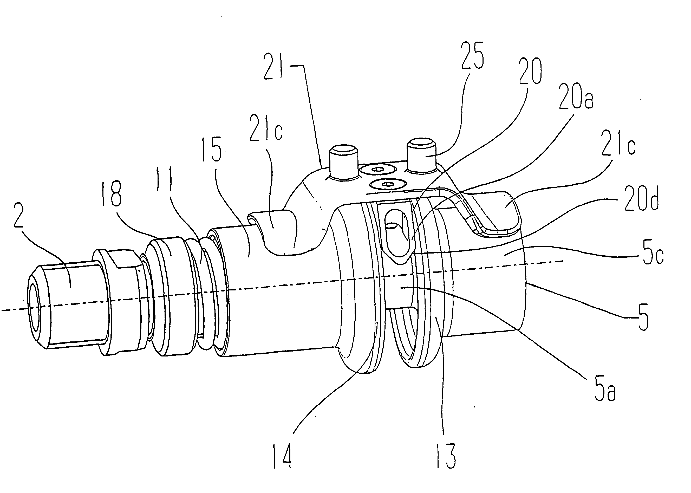
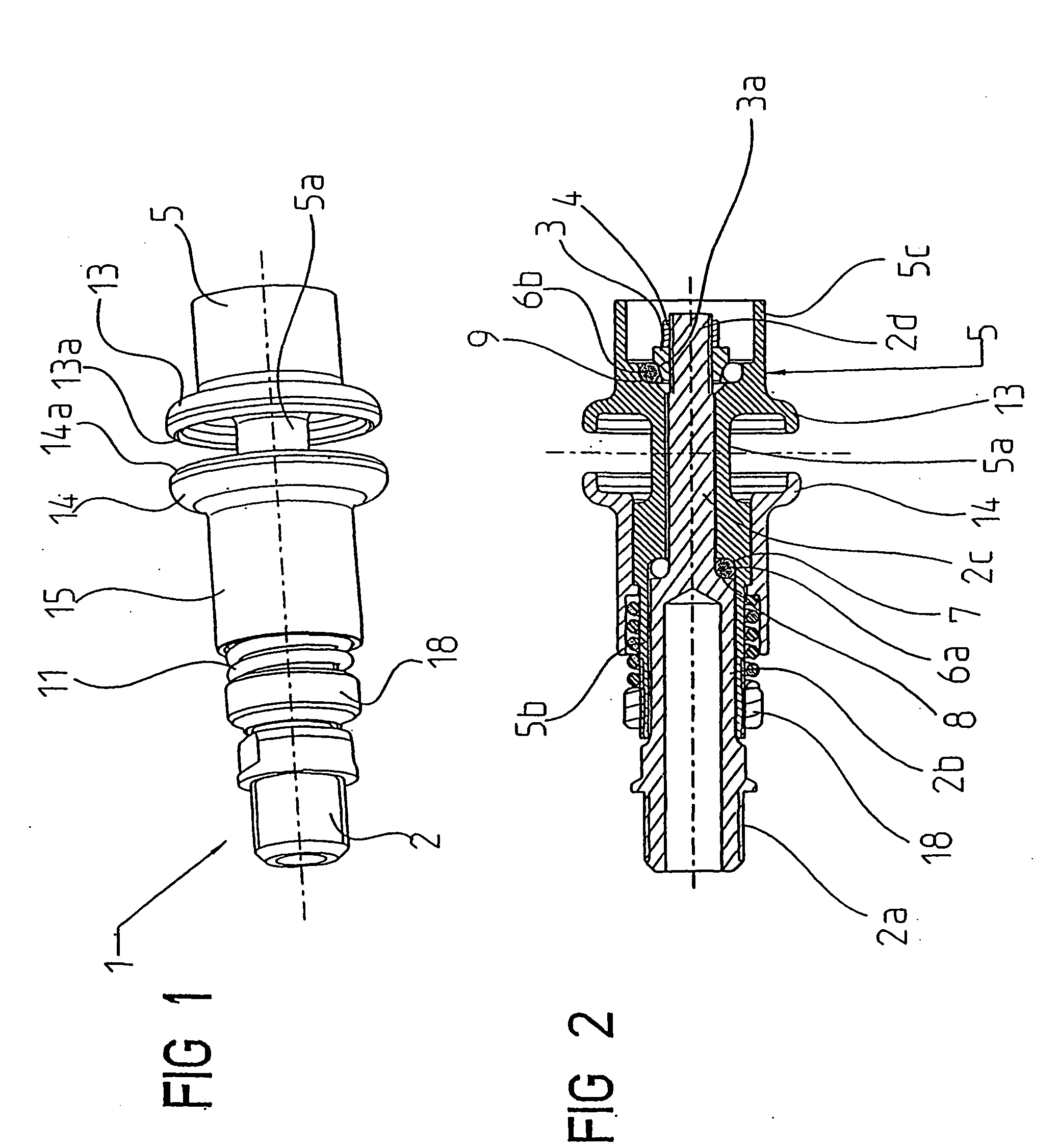
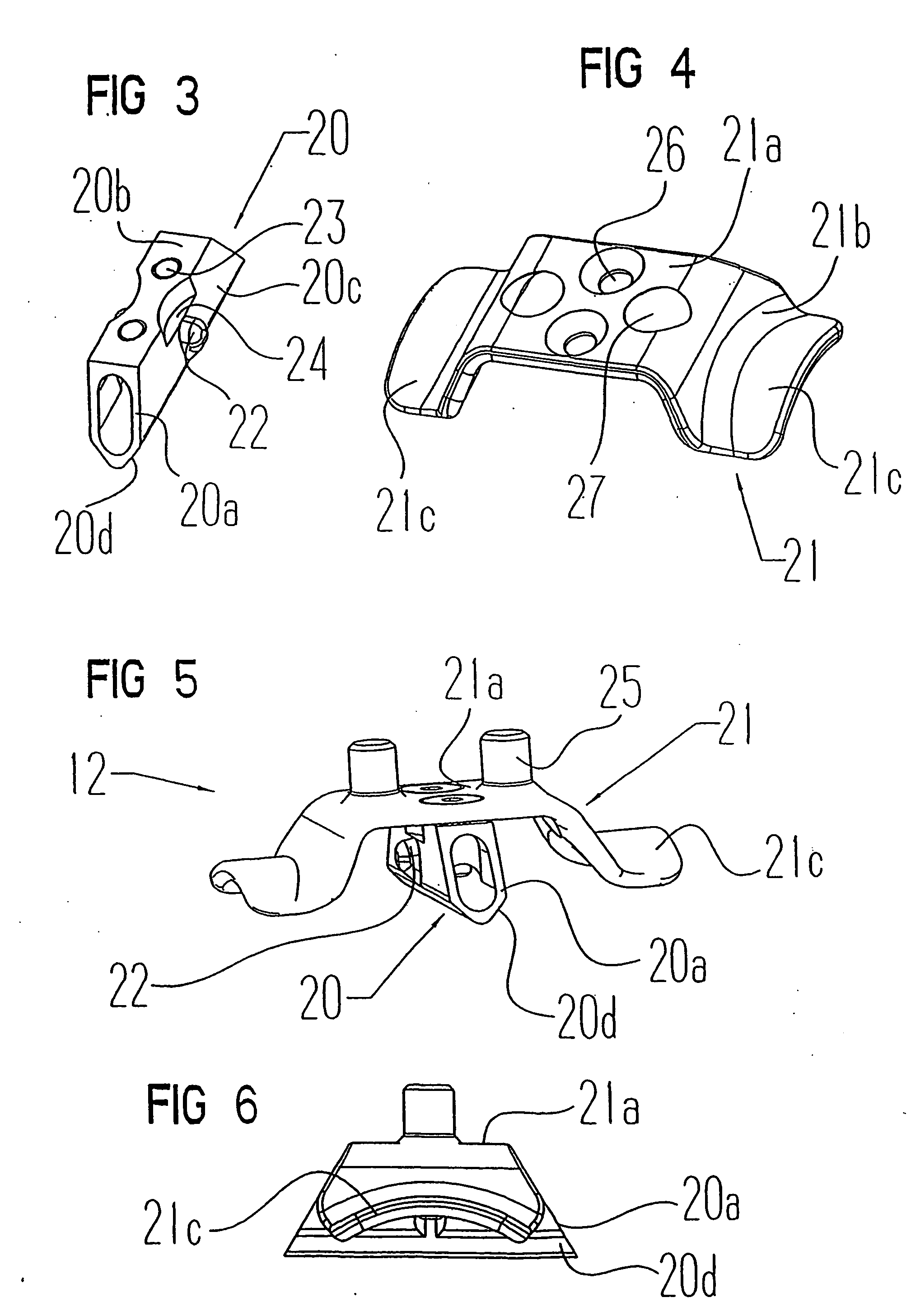
[0027] The parts of the pedal system, which are provided for arrangement or fastening on the bicycle, are hereinafter identified as pedal 1, and those parts, which are provided for fastening on a sole of the shoe, as shoe insert 12.

[0028] The design and the individual parts of the pedal 1 will now be discussed in greater detail in particular with reference to FIGS. 1 and 2. The pedal 1 has an axis part 2 which is fixedly screwed to the crank of a bicycle (not illustrated). The axis part 2 consists of several cylindrical sections, which are arranged concentrically to one another and have varying diameters. The axis part 2 has at its one end in a conventional manner an inner end section 2a with a thread for screwing of the pedal 1 to the crank of the bicycle. The end section 2a is followed by a first bearing section 2b, which is followed by a second bearing section 2c with a smaller diameter. The last section is an outer end section 2d, which has a smaller diameter than the second be...


PUM


Abstract

The invention relates to a pedal system for bicycles that comprises a shoe insert, which can be fastened to the exterior of a shoe and provided with a detent element. The pedal system also comprises a pedal, which can be fastened to the bicycle, can rotate about an axis, and which has a seat for accommodating the detent element. Said detent element can be locked counter to elastic force inside the seat and can be released therefrom by executing a rotating movement. The seat for the detent element is formed between two seat parts which are rotationally symmetrical with regard to the pedal axis and which can be displaced away from one another counter to elastic force in the direction of the pedal axis.

Description

FIELD OF THE INVENTION [0001] The invention relates to a pedal system for bicycles comprising a shoe insert, which can be fastened on a shoe and has a detent element, and a pedal, which can be fastened on the bicycle and can be rotated about an axis, and which pedal has a seat for the detent element, in which seat said detent element can be locked against elastic force, and from which seat same can be released by carrying out a rotating movement. BACKGROUND OF THE INVENTION [0002] Pedal systems have been successful for racing bikes and mountain bikes, which pedal systems consist of shoe inserts fastened on the shoes and of pedals fastened on the bicycle. Pedals which each have locking mechanisms and which are designed correspondingly on two opposing sides, for the releasable locking of the detent element of the shoe insert, are common. Such pedal systems are known, for example, from EP-A-1 167 173 and the EP-A-O 826 589. Since these pedal systems have two locking mechanisms and thus...

Claims


Application Information

Patent Timeline
IPC IPC(8): G05G1/14G05G1/30B62M3/08
CPCB62M3/086Y10T74/217Y10T74/2168
Inventor MALLE, MANFRED
Owner MALLE OEG - TECHNS BURO FUR MASCHEN & ANLAGEBRAU
Why Eureka
Try Eureka