Extendible exhaust nozzle bell for a rocket engine

Inactive Publication Date: 2009-07-16
EADS SPACE TRANSPORTATION
View PDF7 Cites 8 Cited by
  • Summary
  • Abstract
  • Description
  • Claims
  • Application Information

AI Technical Summary

Benefits of technology

[0006]The present invention creates an extendible exhaust nozzle bell of the presupposed type which i

Problems solved by technology

A disadvantage in the known extendible exhaust nozzle bell is a relatively complicated structure of the bellows and the said release mechan

Method used


Image

  • Extendible exhaust nozzle bell for a rocket engine
  • Extendible exhaust nozzle bell for a rocket engine
  • Extendible exhaust nozzle bell for a rocket engine

Examples


Embodiment Construction

[0035]The particulars shown herein are by way of example and for purposes of illustrative discussion of the embodiments of the present invention only and are presented in the cause of providing what is believed to be the most useful and readily understood description of the principles and conceptual aspects of the present invention. In this regard, no attempt is made to show structural details of the present invention in more detail than is necessary for the fundamental understanding of the present invention, the description taken with the drawings making apparent to those skilled in the art how the several forms of the present invention may be embodied in practice.

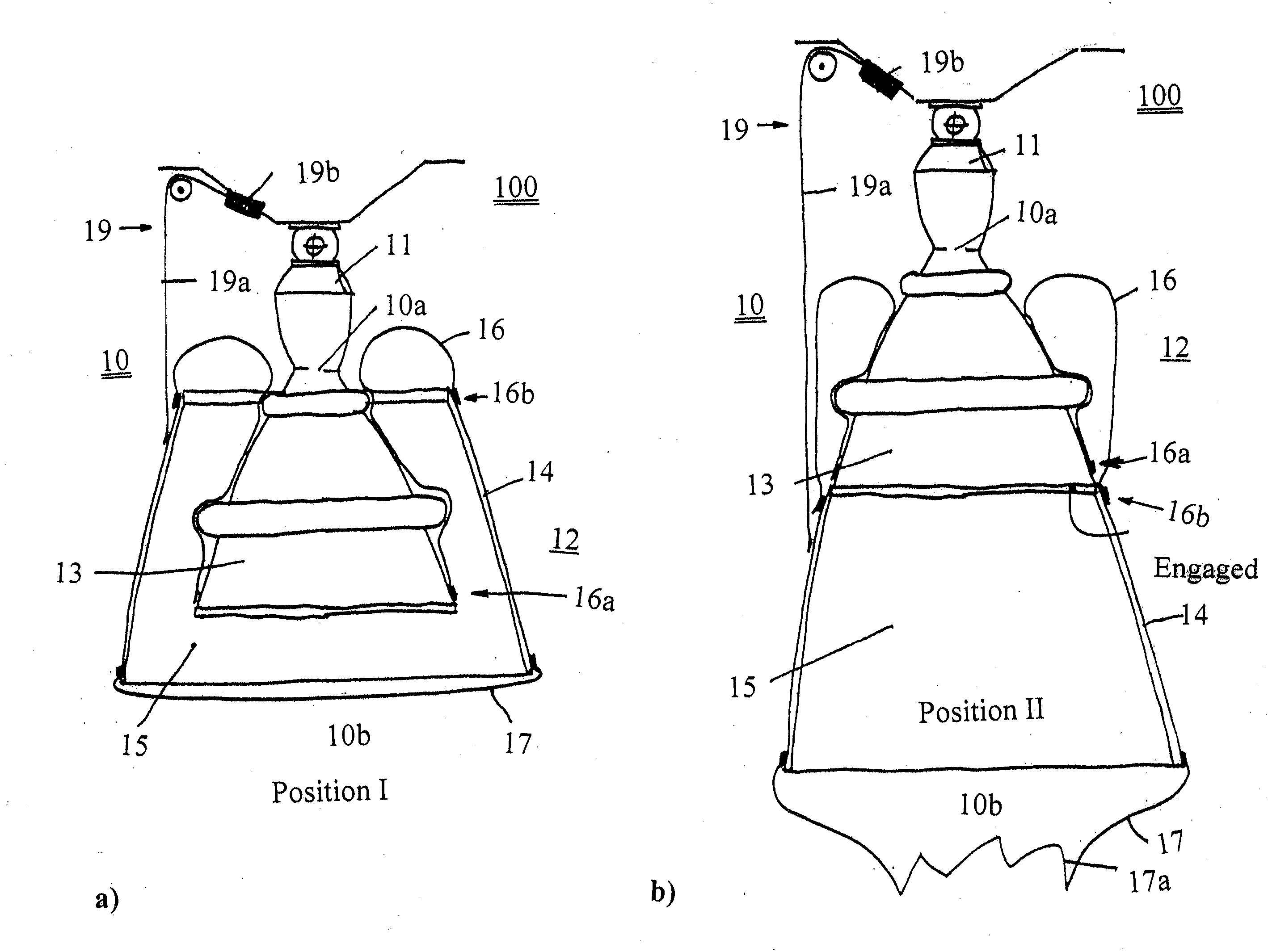
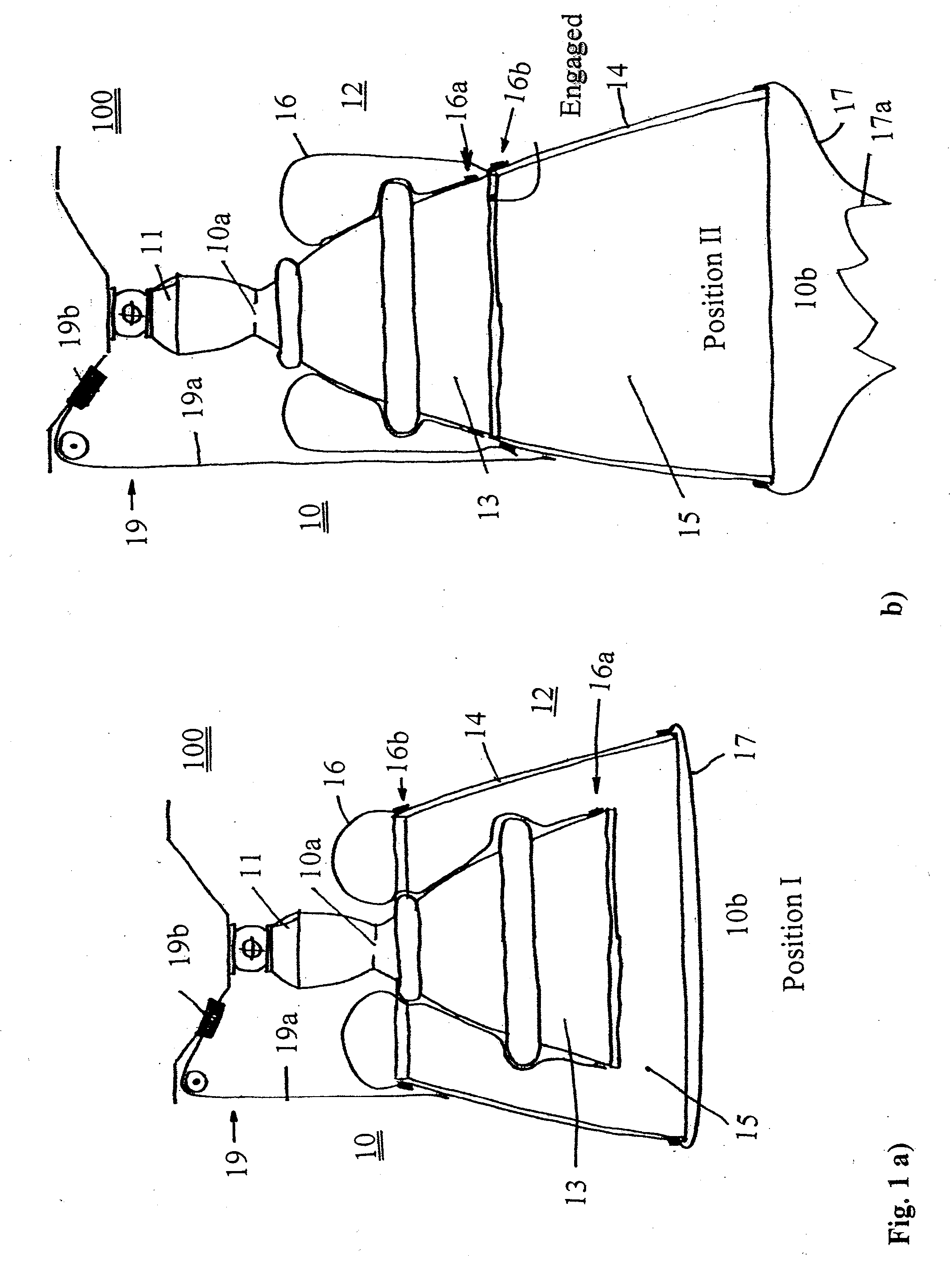
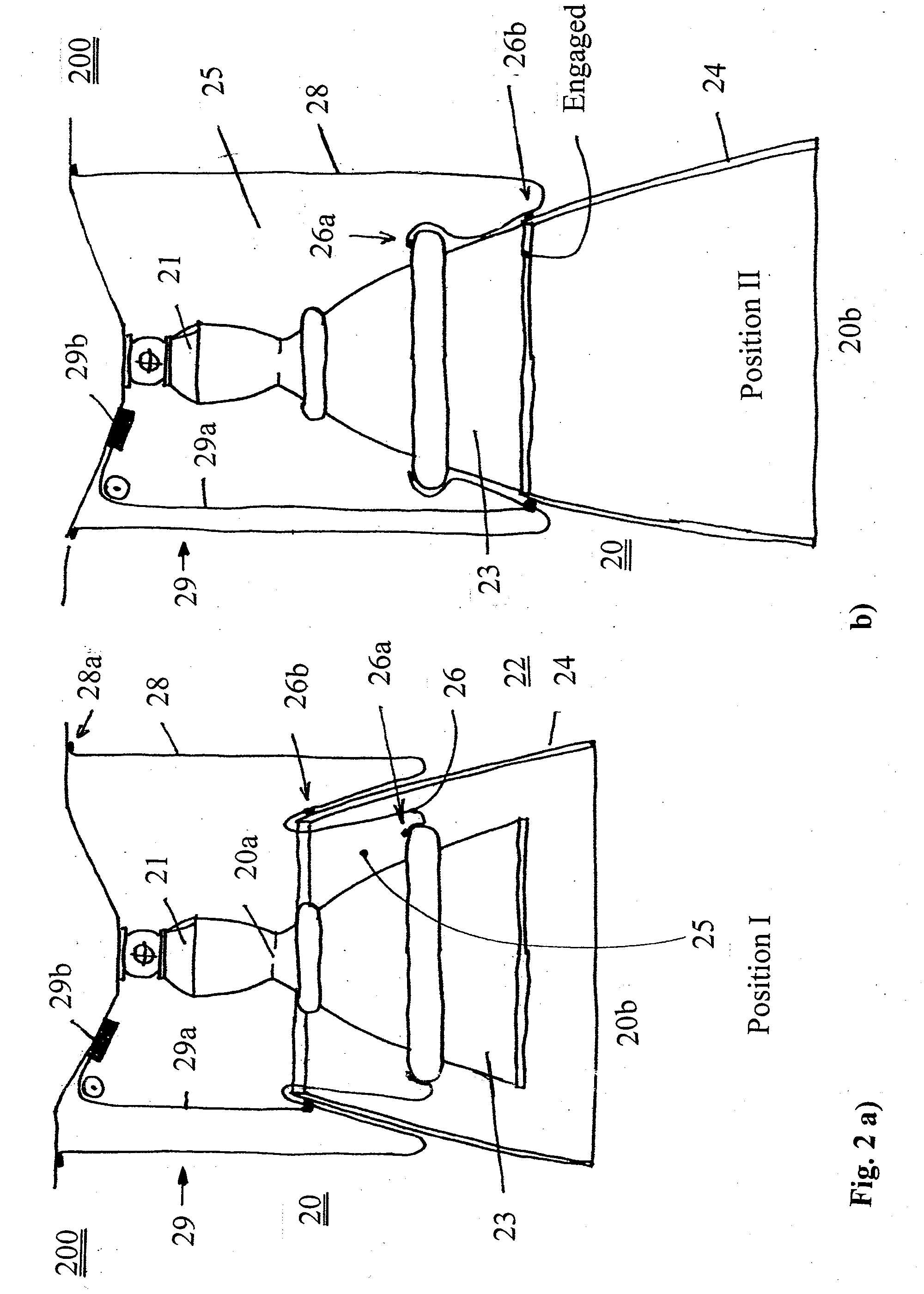
[0036]In the exemplary embodiments of an extendible exhaust nozzle bell for a rocket engine of an aircraft or. spacecraft shown in FIGS. 1 through 4, the reference number 100; 200; 300; 400 means a rear area of the aircraft or spacecraft in the flight direction of the same on which a motor 11; 21; 31; 41 of the rocket eng...


PUM


Abstract

Extendible exhaust nozzle bell for rocket engine of aircraft or spacecraft includes a first part with smaller diameter fixedly arranged on motor of engine and a second part with larger diameter arranged in flexible manner with respect to first part. In a front stowed position, second part is located surrounding first part closer to the rocket motor and, in a rear operating position, first part is arranged further away from the rocket motor. A closed volume that can be acted on by a gaseous fluid causes an extension of the second part of the exhaust nozzle bell from the stowed position into the operating position. The closed volume is formed at least in part by a deformable rolling bellows arrangement coupled between the flexibly arranged second part of the exhaust nozzle bell and a fixed part of the rocket engine or of the aircraft or spacecraft.

Description

CROSS-REFERENCE TO RELATED APPLICATIONS[0001]The present application claims priority under 35 U.S.C. §119 of German Patent Application No. 103 12 419.5, filed on Mar. 20, 2003, the disclosure of which is expressly incorporated by reference herein in its entirety.BACKGROUND OF THE INVENTION[0002]1. Field of the Invention[0003]The invention relates to an extendible exhaust nozzle bell for a rocket engine of an aircraft or spacecraft according to the preamble of claim 1.[0004]2. Discussion of Background Information[0005]An extendible exhaust nozzle bell for a rocket engine is known from U.S. Pat. No. 4,706,886, which comprises a first part with smaller diameter fixedly arranged on the motor of the rocket engine and a second part with larger diameter arranged in a flexible manner with respect to the first part, whereby in a front stowed position (with respect to the flight direction of the aircraft or spacecraft) the second part is located surrounding the first part closer to the rocket...

Claims


Application Information

Patent Timeline
IPC IPC(8): F02K1/00F02K9/97
CPCF02K9/976
Inventor KRETSCHMER, JOACHIM
Owner EADS SPACE TRANSPORTATION
Why Eureka
Try Eureka