Electric lamp with an outer bulb and an integral lamp and a method for its production

a technology of electric lamps and outer bulbs, which is applied in the manufacture of electric discharge tubes/lamps, electrode systems, incandescent lamps, etc., can solve the problems of power supply wires conducting mains voltage exposed, risk of damage to the outer bulb when the lamp is lit, and generally very complex

Inactive Publication Date: 2009-02-05
OSRAM GMBH
View PDF11 Cites 0 Cited by
  • Summary
  • Abstract
  • Description
  • Claims
  • Application Information

AI Technical Summary

Benefits of technology

[0007]With respect to the lamp, the invention is therefore based on the object of providing an electric lamp with a base at one end and with an outer bulb, mounted in a base, and at least one integral lamp, preferably a high-volt halogen lamp, which is arranged within the outer bulb, and at least two power supply wires from the base to the integral lamp, which lamp can be produced in a robust and simple manner and in the case of which the power supply wires are protected reliably from touching contact with the risk of electric shock in the event of breakage of the outer bulb.
[0008]With respect to the method for producing a lamp, the invention is furthermore based on the object of providing a method for producing an electric lamp with a base at one end and with an outer bulb, mounted in a base, and at least one integral lamp, preferably a high-volt halogen lamp, which is arranged within the outer bulb, and at least two power supply wires from the base to the integral lamp, which method makes it possible to produce such a lamp in a simple manner.

Problems solved by technology

However, this is only possible with relatively short power supply wires since otherwise the lamp will be extremely sensitive to vibrations and, in the event of breakage of the outer bulb, the power supply wires conducting mains voltage will be exposed.
This design requires, in order to pass the power supply wires through the vitreous plate-like stand, a three-part design and is generally very complex as a result of the combination of metallic and vitreous components.
The mounting clip is fitted on the vitreous stand of the outer bulb, which is very involved, however, since the vitreous stand represents a very complex component which comprises, for example, an exhaust tube and fused-in power supply wires.
When using a metallic mounting clip, there is in addition the risk of damage to the outer bulb when the lamp is fitted or operated and it is necessary to ensure that no live parts come into contact with the clip.
Furthermore, the metallic holder is visually very obvious and considerably disrupts the transparent outward appearance known from a conventional incandescent lamp.

Method used


Image

  • Electric lamp with an outer bulb and an integral lamp and a method for its production
  • Electric lamp with an outer bulb and an integral lamp and a method for its production
  • Electric lamp with an outer bulb and an integral lamp and a method for its production

Examples


second embodiment

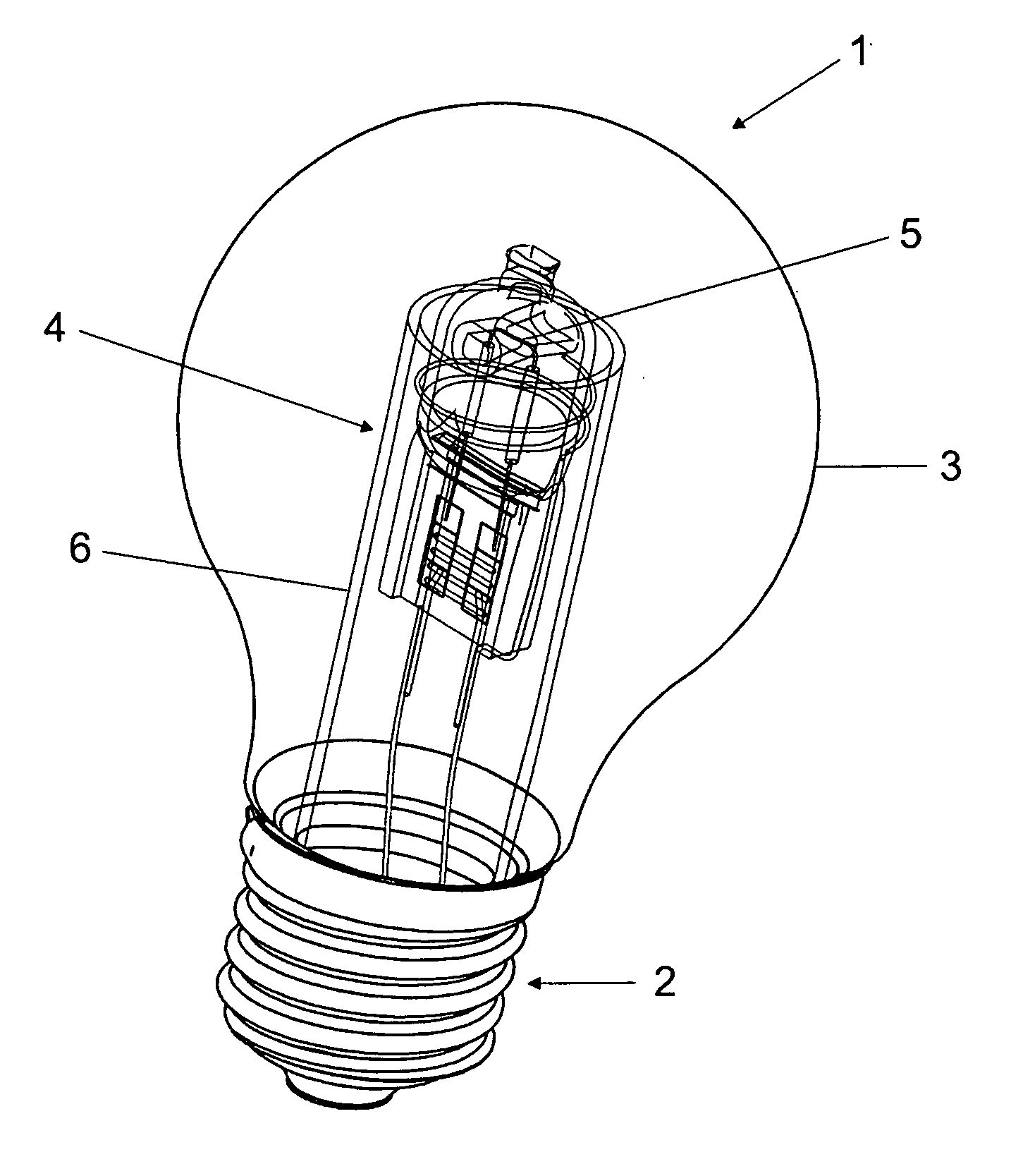
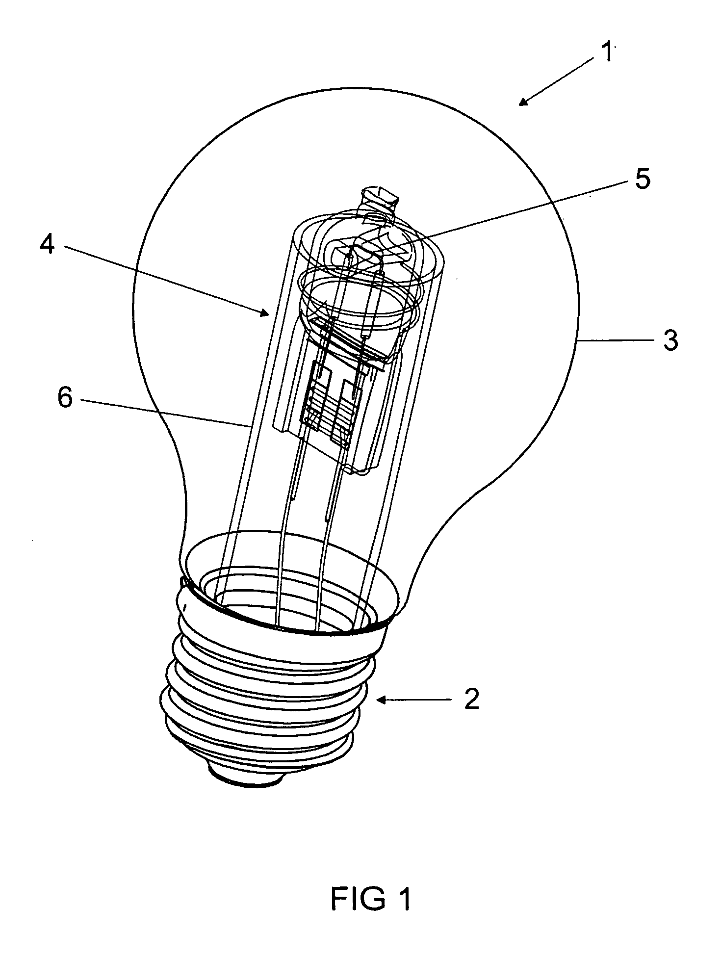
[0068]FIG. 4 shows a lamp 1 according to the invention in accordance with a second embodiment in a side view. The basic design with the base 2, the outer bulb 3, the cylindrical bulb 6 which is fused to the outer bulb 3, and the integral lamp 4 corresponds to the lamp 1 shown in FIG. 1. In contrast to the first exemplary embodiment, however, in this case the cylindrical bulb 6 is only guided as far as the lower edge of the bulb 14 of the integral lamp 4. A holding apparatus 16, in which the integral lamp 4 is held, is arranged in the cylindrical bulb 6.

[0069]The holding apparatus 16 substantially comprises two holding elements 17, which surround the base 8 of the integral lamp 4 and comprise two holding elements 18 in the form of circular arcs which fix the holding apparatus 16 in the cylindrical bulb 6.

[0070]As can be seen from FIG. 5, which shows a horizontal section through the base 8 of the integral lamp 4, the base 8 of the integral lamp 4 typically has a double T cross section...

fourth embodiment

[0080]FIG. 9 shows a lamp 1 according to the invention in accordance with a fourth embodiment in a lateral illustration. The basic design with a base 2, an outer bulb 3, a cylindrical bulb 6 fused to the outer bulb 3 and an integral lamp 4 corresponds to the lamp 1 shown in FIG. 1. In contrast to the first exemplary embodiment, however, in this case the cylindrical bulb 6 is only guided as far as the lower edge 33 of the integral lamp 4. A holding apparatus 16 is arranged in the cylindrical bulb 6.

[0081]As can be seen from FIG. 10, which shows the holding apparatus 16 as a detail illustration and rotated through 90° with respect to FIG. 9, the holding apparatus 16 substantially comprises a holding clip 34, which holds the base 8 of the integral lamp 4, and two holding elements 18 in the form of circular arcs which fix the holding apparatus 16 in the cylindrical bulb 6. The radius of the holding elements 18 in the form of circular arcs, of which only the front one is illustrated here...


PUM


Abstract

The invention relates to an electric lamp (1) with a base at one end and with an outer bulb (3), mounted in a base (2), and at least one integral lamp (4), preferably a high-volt halogen lamp, which is arranged within the outer bulb (3), and at least two power supply wires (9, 9a, 9b) from the base (2) to the integral lamp (4). The invention likewise relates to a method for producing such a lamp. The at least two power supply wires (9, 9a, 9b) are surrounded by a preferably cylindrical bulb (6) made from nonconductive material, and the cylindrical bulb (6) is connected, preferably fused, to the outer bulb (3).

Description

TECHNICAL FIELD[0001]The invention relates to an electric lamp with a base at one end and with an outer bulb, mounted in a base, and at least one integral lamp, preferably a high-volt halogen lamp, which is arranged within the outer bulb, and at least two power supply wires from the base to the integral lamp. The invention furthermore relates to a method for producing an electric lamp with a base at one end and with an outer bulb, mounted in a base, and at least one integral lamp, preferably a high-volt halogen lamp, which is arranged within the outer bulb, and at least two power supply wires leading from the base to the integral lamp.PRIOR ART[0002]As a result of their long life and pleasant light quality, halogen incandescent lamps are increasingly preferred to conventional incandescent lamps. In order to make it possible to replace existing incandescent lamps with halogen incandescent lamps as simply as possible and at the same time to maintain the visual appearance of a conventi...

Claims


Application Information

Patent Timeline
Patent Type & Authority Applications(United States)
IPC IPC(8): H01J5/48H01J9/00
CPCH01J61/34Y02B20/125H01K1/34Y02B20/00
Inventor NAUJOKS, BERNDSTARK, ROLAND
Owner OSRAM GMBH
Why Eureka
Try Eureka