
Rattle-free component pairing

Inactive Publication Date: 2010-12-30
GETRAG GETRIEBE & ZAHNRADFABRIK HERMANN HAGENMEYER GMBH & CO KG
View PDF8 Cites 9 Cited by
  • Summary
  • Abstract
  • Description
  • Claims
  • Application Information

AI Technical Summary

Benefits of technology

[0028]If the motor vehicle gearbox is designed as a countershaft-type multi-stage gearbox, one or more wheel sets (in each case with one loose wheel and at least one fixed wheel) may have a component pairing according to the invention. The tendency of such gearboxes to rattle may be reduced by means of the measures according to the invention to such an extent that the multi-stage gearbox can be designed without a dual-mass flywheel. This leads to a considerable increase in efficiency because the overall mass, or the so-called mass factor, can be reduced. The considerable costs for a dual-mass flywheel can also be saved in this way. Furthermore, the disturbing tendency for vibration build-up in a dual-mass flywheel can be reduced. Furthermore, as a result of the reduction in the rotating masses to be accelerated, better response behaviour can be obtained (the vehicle equipped in this way “responds better to the throttle”). Here, a drivetrain having a multi-stage gearbox of said type may have an adapted starting clutch which has an integrated torsional damper (torsion-damped clutch disc). The multi-stage gearbox may be a manual, an automatic or a dual-clutch gearbox.
[0191]The anti-rattle component is preferably designed as an annular element. The ratio of outer diameter of the annular element preferably lies in the range from 100:50 to 100:95, in particular in the range from 100:60 to 100:85, in particular in the range from 100:70 to 100:80. In this way, the anti-rattle component may be formed with a low weight.

Problems solved by technology

One of the main problems with mechanical component pairings of said type is the so-called rattling phenomenon.
The rattling (also referred to as undesirable vibrations) is generated in that, on account of the vibration excitation, the driving component is decelerated but the driven component (for example a loose wheel) continues to rotate with an imparted rotational movement and is decelerated only as a result of friction and drag torque effects.
Such dual-mass flywheels are however expensive in terms of the installation space taken up, the necessary additional weight and in terms of costs.
These measures are also disadvantageous.
Disadvantages here are often the reduced efficiency and the generation of other undesired noises (such as for example whining).

Method used


Image

  • Rattle-free component pairing
  • Rattle-free component pairing
  • Rattle-free component pairing

Examples


Embodiment Construction

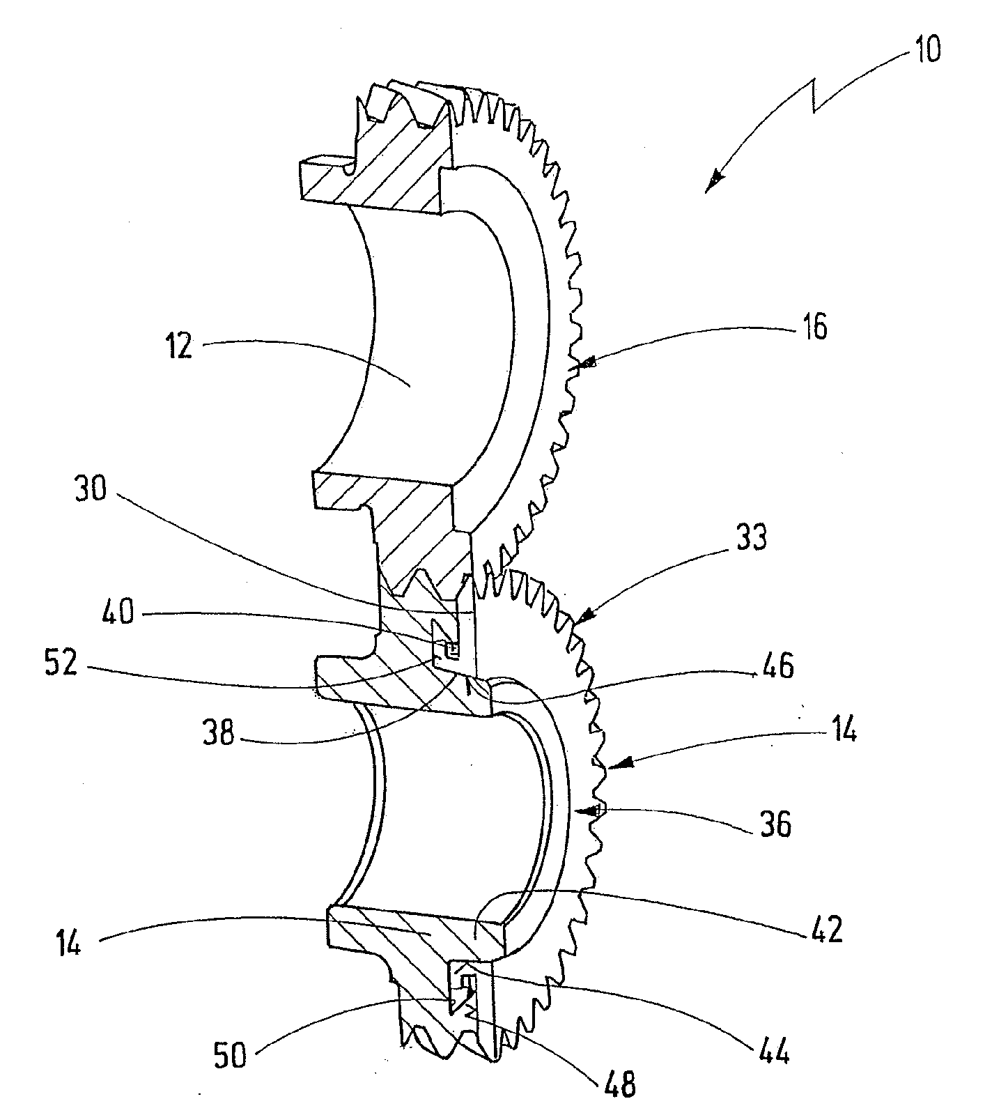
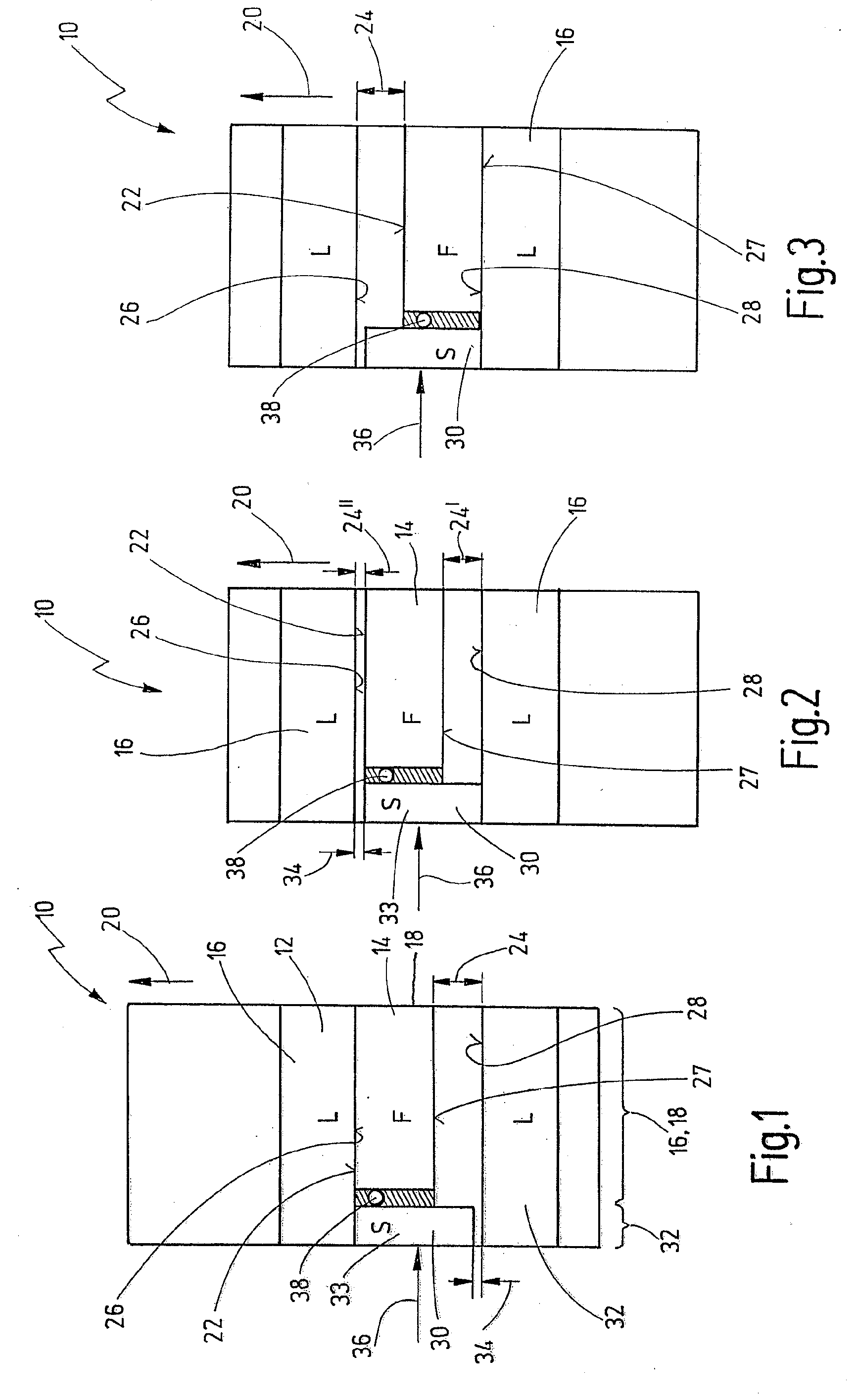
[0235]A first embodiment of a mechanical component pairing is illustrated in FIGS. 1 to 3 and is denoted generally by 10.

[0236]The component pairing 10 has a first component 12 in the form of a loose wheel and a second component 14 in the form of a fixed wheel. In the present case, the fixed wheel 14 is the driving component. The loose wheel 12 has a first component toothing 16. The fixed wheel 14 has a second component toothing 18.

[0237]The loose wheel 12 is driven by means of the fixed wheel 14 in a drive direction 20. Here, a thrust flank 22 of the second toothing 18 makes contact with a rear flank 26 of the first toothing 16.

[0238]The toothings 16, 18 are formed with a certain tooth flank play, which is denoted in FIG. 1 by 24.

[0239]In the present case, the tooth flank play 24 is the distance between a rear flank of the second toothing 18 and a thrust flank 28 of the first toothing.

[0240]Toothings of said type are generally known. On account of the tooth flank play 24, so-called...


PUM


Abstract

A component pairing comprises a first component with a first component toothing and comprises a second component with a second component toothing which is in engagement with the first component toothing in order to be able to transmit a drive force in a drive direction via the component toothings. The first component is also assigned a first anti-rattle toothing. An anti-rattle component is fastened to the second component, which anti-rattle component has a second anti-rattle toothing which is in engagement with the first anti-rattle toothing. The anti-rattle component is mounted so as to be displaceable relative to the second component in the drive direction. The second component and the anti-rattle component are assigned in each case one friction section. The friction sections are in frictional engagement with one another.

Description

CROSS-REFERENCE TO RELATED APPLICATIONS[0001]This is a continuation application of International patent application PCT / EP 2008 / 010988, filed Dec. 21, 2008, claiming the priorities of German patent application DE 10 2007 063 524, filed Dec. 27, 2007, and of German utility application DE 20 2008 010745, filed Aug. 7, 2008, the entireties of which are incorporated by reference herein.BACKGROUND OF THE INVENTION[0002]The present invention relates to a mechanical component pairing comprising a first component with a first component toothing and comprising a second component with a second component toothing which is in engagement with the first component toothing in order to be able to transmit a drive force in a drive direction via the component toothings.[0003]Component pairings of said type are generally known, for example in the form of gearwheel pairings and / or the pairing of a toothed rack with a gearwheel. Such component pairings are often used in drivetrains of motor vehicles, fo...

Claims


Application Information

Patent Timeline
IPC IPC(8): F16H55/18
CPCF16H55/14Y10T74/19898F16H57/0006F16H55/18Y10T74/19623F16H2057/0012
Inventor LANG, CLAUS-HERMANN
Owner GETRAG GETRIEBE & ZAHNRADFABRIK HERMANN HAGENMEYER GMBH & CO KG
Learn More