Light source module

Active Publication Date: 2021-01-21
CORETRONIC
View PDF0 Cites 0 Cited by
  • Summary
  • Abstract
  • Description
  • Claims
  • Application Information

AI Technical Summary

Benefits of technology

[0007]Based on the above, in the light source module of an embodiment of the disclosure, the main portion of the encapsulation layer is disposed between the light-emitting element and the reflecting element, and the light-emitting element and the reflecting element are disposed in the central position of the main portion. With the plurality of first inclined ridges around the central position of the main portion and the angle included between the first inclined ridge and the surface of the substrate being less than 90 degrees, the light emitted by the light-emitting element can be prevented from

Problems solved by technology

However, traveling of a portion of the light emitted from the light-emitting diodes in the encapsulation layer, the light is still transmitted laterally (e.g., perpendicular to the light emitting direction) to an adjacent or farther light source (i.e., another light-emitting diode) area through multiple times of total internal reflection in the encapsulation layer, causing an edge halo eff

Method used


Image

  • Light source module
  • Light source module
  • Light source module

Examples


Example

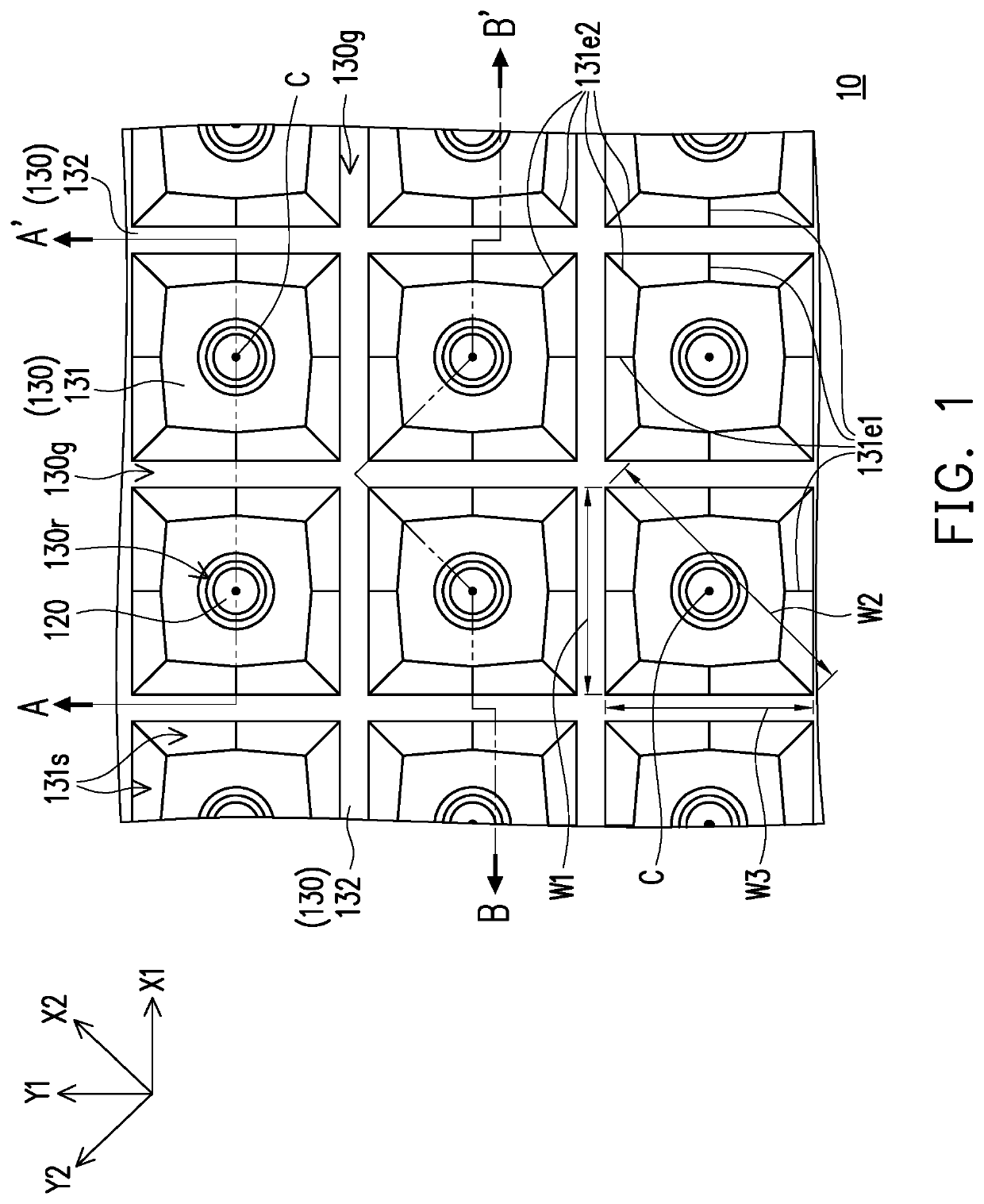
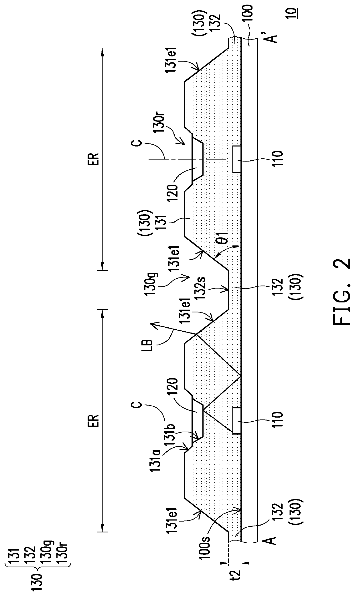
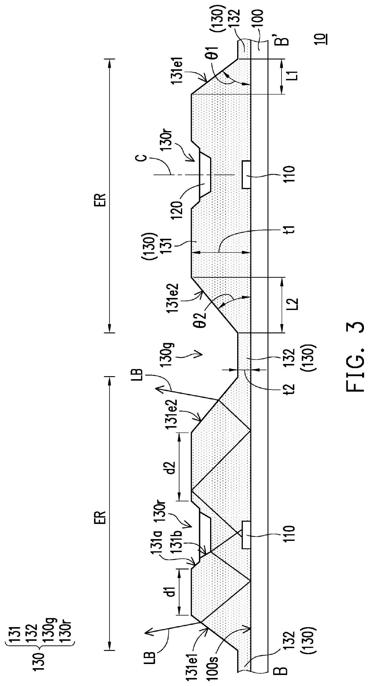
[0021]FIG. 1 is a schematic top view of a light source module according to the first embodiment of the disclosure. FIG. 2 is a schematic cross-sectional view of the light source module of FIG. 1 taken along a line A-A′. FIG. 3 is a schematic cross-sectional view of the light source module of FIG. 1 taken along a line B-B′. In particular, a substrate 100 shown in FIG. 2 and FIG. 3 is omitted in FIG. 1.

[0022]Referring to FIG. 1, FIG. 2, and FIG. 3, a light source module 10 includes a substrate 100, a plurality of light-emitting elements 110, a plurality of reflecting elements 120, and an encapsulation layer 130. The plurality of light-emitting elements 110 are disposed on a surface 100s of the substrate 100. The plurality of reflecting elements 120 are respectively overlapped with the plurality of light-emitting elements 110 in a direction perpendicular to the surface 100s of the substrate 100. The encapsulation layer 130 is disposed between the plurality of reflecting elements 120 an...

Example

[0038]FIG. 4 is a schematic top view of a light source module according to the second embodiment of the disclosure. FIG. 5 is a schematic cross-sectional view of the light source module of FIG. 4 taken alone a line C-C′. In particular, the substrate 100 of FIG. 5 is omitted in FIG. 4. Referring to FIG. 4 and FIG. 5, the difference between a light source module 11 in the embodiment and the light source module 10 of FIG. 1 is that the structure of the encapsulation layer is different. Specifically, an encapsulation layer 130A of the light source module 11 does not have the connection 132 shown in FIG. 1, and a plurality of main portions 131A of the encapsulation layer 130A are directly connected to each other. In other words, the inclined surface 131s, the first inclined ridge 131e1, and the second inclined ridge 131e2 of the main portion 131A alone may define a first groove 130g-1 of the encapsulation layer 130A.

[0039]In the embodiment, the first inclined ridge 131e1, the second incl...

Example

[0040]FIG. 6 is a schematic top view of a light source module according to the third embodiment of the disclosure. FIG. 7 is a schematic cross-sectional view of the light source module of FIG. 6 taken along a line D-D′. In particular, the substrate 100 of FIG. 7 is omitted in FIG. 6. Referring to FIG. 6 and FIG. 7, the difference between a light source module 12 in the embodiment and the light source module 10 of FIG. 1 is that the structure of the main portion is different. Specifically, a length L2′ of the orthogonal projection of a second inclined ridge 131e2A of a main portion 131B of an encapsulation layer 130B on the surface 100s of the substrate 100 is greater than the length L2 of the orthogonal projection of the second inclined ridge 131e2 of the main portion 131 of the encapsulation layer 130 on the surface 100s of the substrate 100 in FIG. 3.

[0041]In the embodiment, a distance d2′ in the direction X2 (or direction Y2) between the end of the second inclined ridge 131e2A aw...


PUM


Abstract

The disclosure provides a light source module including a substrate, multiple light-emitting elements, multiple reflecting elements, and an encapsulation layer. The reflecting elements and light-emitting elements are disposed in stack arrangement in the direction perpendicular to the substrate surface, respectively. The encapsulation layer disposed between the reflecting elements and light-emitting elements includes multiple first grooves and main portions. The first grooves located between the light-emitting elements are connected to each other. The main portions cover the light-emitting elements, and the reflecting elements and the light-emitting elements are disposed in the central position of the main portions having multiple first inclined ridges disposed around the central position to define the first grooves in the first direction parallel to the extending direction of the substrate surface. The first angle included between the first inclined ridge and the surface of the substrate is less than 90 degrees.

Description

CROSS-REFERENCE TO RELATED APPLICATION[0001]This application claims the priority benefit of U.S. provisional application Ser. No. 62 / 874,508, filed on Jul. 16, 2019, and China application serial no. 202020824525.8, filed on May 18, 2020. The entirety of each of the above-mentioned patent applications is hereby incorporated by reference herein and made a part of this specification.BACKGROUNDTechnical Field[0002]The disclosure relates to a backlight module, and particularly to a light source module.Description of Related Art[0003]With increasing applications of non-self-luminous display devices, such as liquid crystal display devices, the design of backlight modules also needs to be adjusted for different applications. In order to meet the display requirements of large size, high dynamic range (HDR), and high contrast, a backlight module needs to be equipped with the local dimming function. Therefore, direct-lit backlight modules using light-emitting diodes as the main light source ha...

Claims


Application Information

Patent Timeline
IPC IPC(8): H01L33/54H01L33/60
CPCH01L33/54H01L33/60H01L25/0753
Inventor YANG, WEN-HSUNHUANG, YU-ANLIN, SHIH-YI
Owner CORETRONIC
Why Eureka
Try Eureka