Color changing light object and user interface for same

a technology of user interface and light object, which is applied in the direction of free standing, semiconductor devices for light sources, light and heating apparatus, etc., can solve the problems of inability to adapt to the needs of each of the foregoing lighting devices, the interface of the known devices described above is not particularly versatile or user-friendly, and the device includes a user interface or a memory card

Inactive Publication Date: 2006-07-20
SC JOHNSON & SON INC
View PDF36 Cites 73 Cited by
  • Summary
  • Abstract
  • Description
  • Claims
  • Application Information

AI Technical Summary

Benefits of technology

[0017] Certain disclosed light objects include what will hereinafter be referred to as a “light pipe” which covers the base, electronics on the base and the light sources and is disposed between the base and the cavity of the housing. In certain arrangements, the light pipe is shaped to closely match the shape of the housing cavity although it is preferably spaced apart from the interior walls of the housing that define the cavity. Preferred light pipes include either roughened interior or exterior surfaces to aid in light diffusion. This roughening of the interior or exterior surface enhances light diffusion. A lambertian or near-lambertian surface on the light pipe can be easily achieved by sandblasting or roughening using a conventional scouring pad made from a nylon web and coarse mineral abrasives. Other techniques for roughening the interior or exterior surface of a light pipe or the interior or exterior surface of the light object housing to enhance light diffusion will be apparent to those skilled in the art.
[0024] In another arrangement, the user interface comprises a control switch and a freeze button. With the control switch of this arrangement, a user can select between an OFF position, in which no light is emitted from the light object, a first light show position, in which the light object is illuminated in a first preprogrammed light show, a second light show position, in which the light object is illuminated in a second preprogrammed light show, a third light show position, in which the light object is illuminated in a third preprogrammed light show, a steady illumination mode, in which the second light source emits a steady (i.e., substantially constant intensity) illumination, and a flicker illumination mode, in which the second light source emits a flickering (i.e., changing intensity) illumination. With the freeze button, the user can freeze a light show at a desired point in the light show, when the control switch is in one of the first, second, or third light show positions.
[0028] In another aspect, the light object includes a transceiver for communicating with a removable remote control-type interface as described above. In another related aspect, the light object includes a transceiver for communicating with another similarly equipped light object. Thus, two light objects can communicate with each other and the light shows presented on the light objects can be synched with one another. In a related aspect, more than two light objects may be incorporated in a “system” used in a home that communicate with each other and present light shows in sync with one another. In another related aspect, interfaces for light objects can be capable of downloading light shows from a personal computer in a wireless fashion thereby eliminating the need for a USB port for Internet downloading.
[0036] One preferred light object embodiment includes a vertical outer housing or shell with an interior cavity and a bottom opening. A base is mateably received and fits within the opening. The base supports an interface that comprises a push button pad and a circuit board. One or more frame members can be used to secure the base within the opening and to further support a light pipe that fits over the base. The light pipe can serve two functions. First, the light pipe can serve as a cover for the electronic components mounted to the base to keep them hidden from view and, second, the light pipe can be used to diffuse light. Again, either the outer or inner surface of the light pipe can be roughened to form a lambertian or near-lambertian surface for diffusing light. In this way, the light pipe can be roughened and the interior or exterior surfaces of the housing need not be roughened. As an alternative to roughening either the interior or exterior surfaces of the light pipe, the interior surface or the exterior surface of the housing can be roughened and the light pipe can be used simply to hide the electronic components. This disclosure is not limited to light objects with only one roughened surface; it may be advantageous to roughen more than one surface.

Problems solved by technology

However, there are deficiencies associated with each of the foregoing lighting devices.
For example, the known interfaces for the devices described above are not particularly versatile or user friendly.
None of the disclosed devices include a user interface or a memory card that may be easily removed and replaced with a new interface or memory card.
None of the above devices include a user friendly interface that makes it easy to select a particular light show, that makes it easy to pause a show in progress or that makes it easy to adjust the intensity of a show in progress.
Further, none of the above devices include a remote control.
Similarly, none of the disclosed devices include a wireless communication capability that would enable two devices disposed in a room or on a mantle to be synchronized with each other.
None of the above devices are capable of downloading new information or light shows from the internet or from the memory of a PC.
Sound is not an option with the currently available devices.
The known devices are not responsive to environmental conditions such as ambient sound, temperature or light.

Method used


Image

  • Color changing light object and user interface for same
  • Color changing light object and user interface for same
  • Color changing light object and user interface for same

Examples


Embodiment Construction

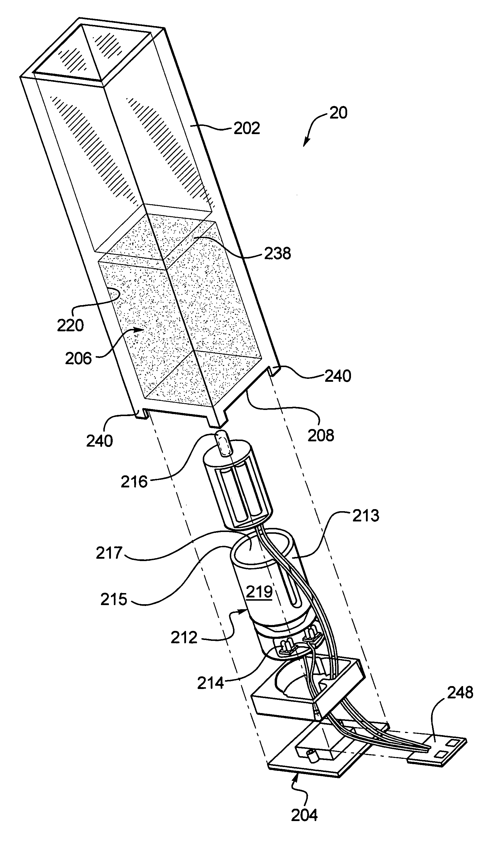
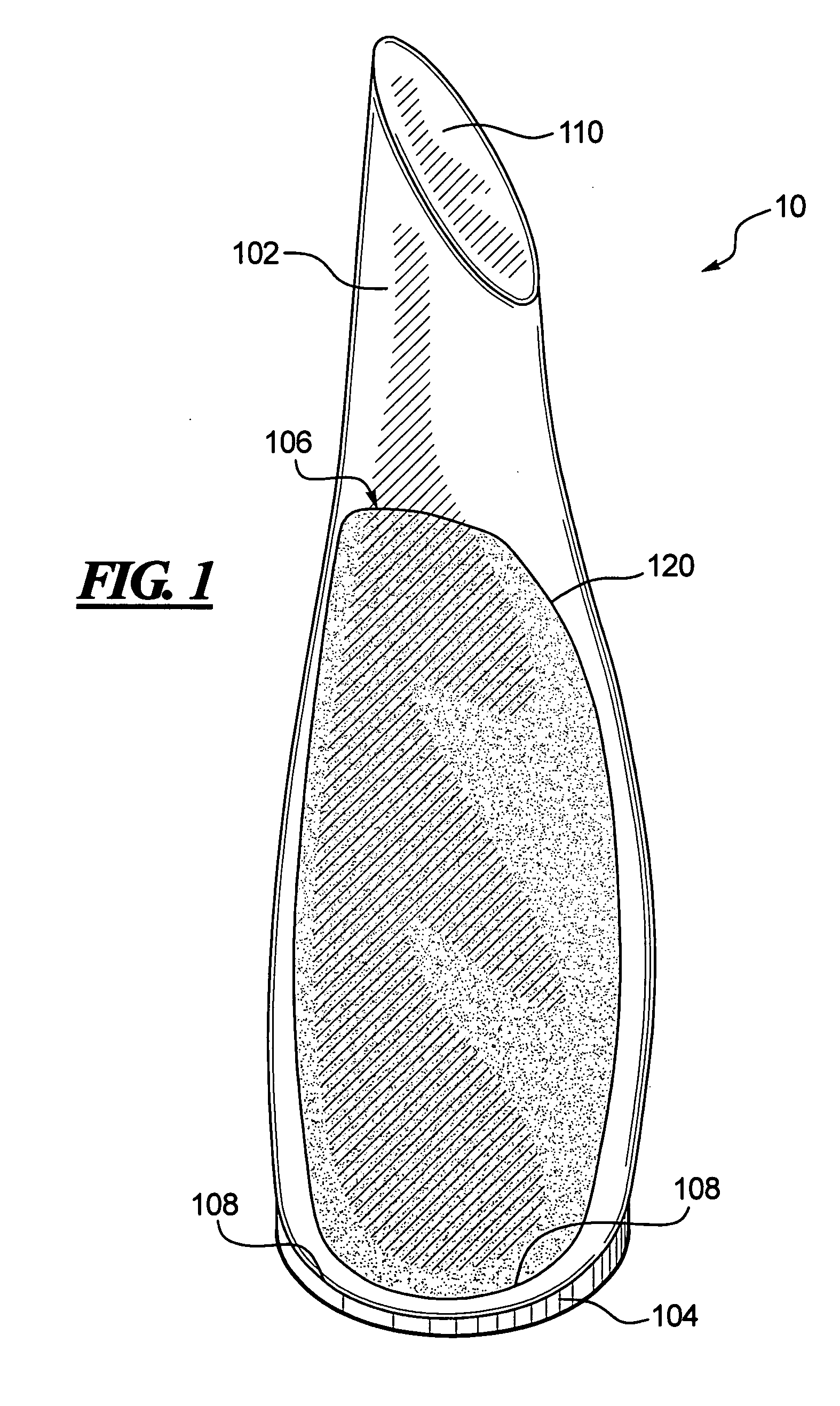
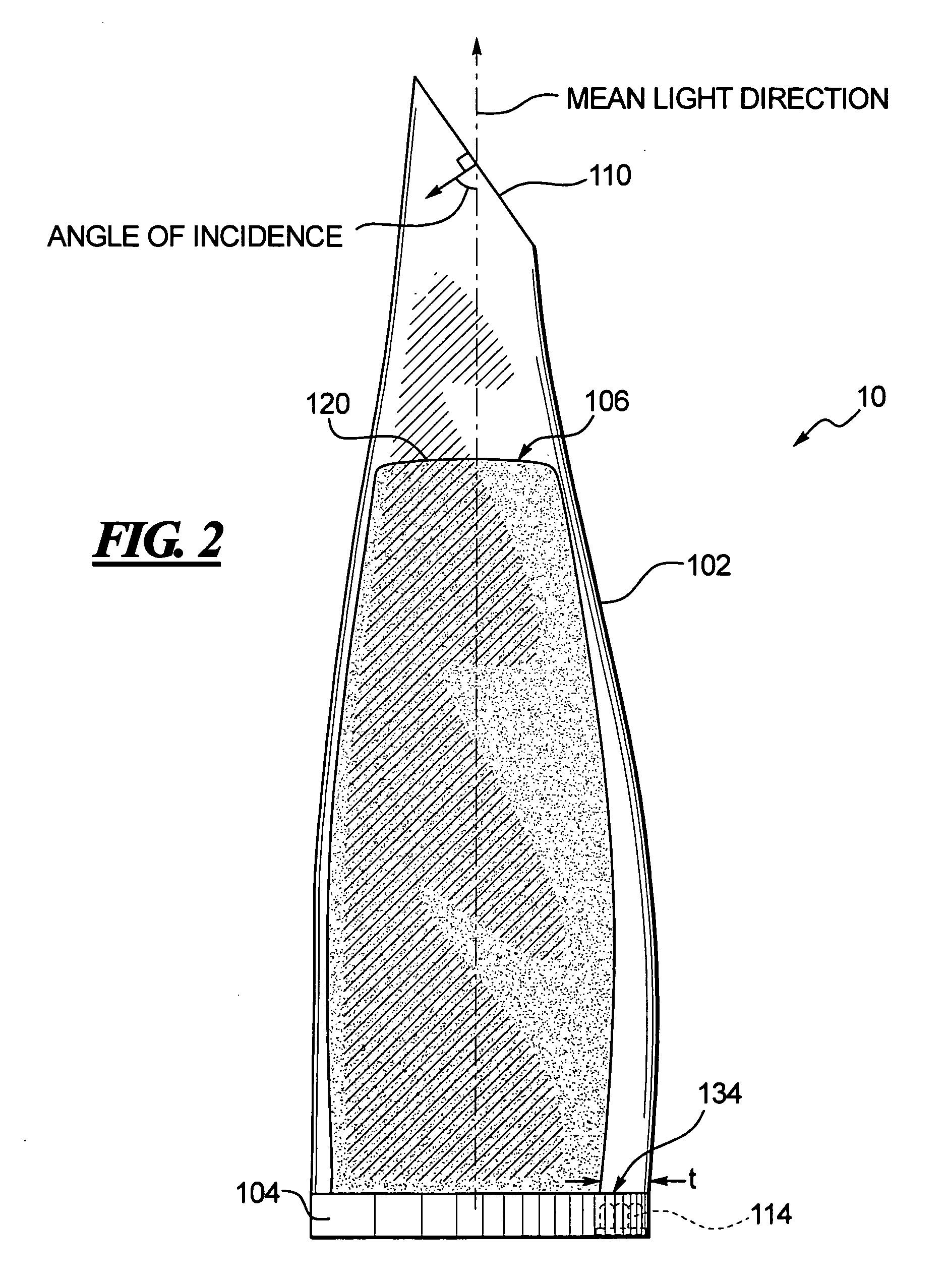
[0065] A curved light object 10 according to one preferred embodiment is shown in FIGS. 1-4. The light object 10 generally comprises a translucent housing 102 with a base 104 attachable thereto by one or more removable fasteners (not shown). The housing 102 of this embodiment is generally in the shape of an amphora (but without any handles) and has an internal cavity 106 formed therein, which defines an opening 108 in the housing 102. The surface 120 of the cavity 106 is sandblasted to provide a roughened, light-diffusing surface. The base 104 substantially covers the opening 108 in the housing 102 (when mounted to the housing), and a protruding portion 112 of the base 104 extends into the cavity 106. The fasteners used to attach the housing 102 to the base 104 preferably fasten to legs (not visible in the drawings) protruding from the bottom of the housing 102 around the opening 108. Of course, numerous other methods of attaching the housing 102 and base 104 could be used, as will ...


PUM


Abstract

Illuminated, decorative light objects are disclosed that provide at least one aesthetic lighting display or light show, and to a user interface for the same. A disclosed decorative light object includes a translucent housing. The housing has a bottom opening leading into a cavity. The object also includes a base assembly that covers the bottom opening of the housing. The base assembly includes a user interface. The user interface includes light show circuitry, memory for storing a plurality of light shows, switches or buttons for recalling the light shows from the memory and at least one light group comprising red, green and blue lights. The switches of the user interface are supported in the bottom opening. The light show circuitry, memory and lights are supported within the cavity. Preferably, a translucent light pipe with a roughened lambertian outer surface covers and hides the circuitry and the lights. As the light shines through the light pipe it is diffused thereby creating a warm glowing appearance.

Description

BACKGROUND [0001] 1. Technical Field [0002] Decorative light objects used as home furnishings and user interfaces for the same are disclosed. The disclosed decorative light objects provide one or more aesthetic lighting displays or light shows. Disclosed user interfaces that fit in the base of a decorative object provide one or more aesthetic lighting displays or light shows through the decorative light object. [0003] 2. Description of the Related Art [0004] Various decorative illuminated objects are known in the art, which display one or more lighting effects. For example, U.S. Pat. No. 6,801,003 (“Schanberget”) discloses lighting systems for swimming pools, wall-mounted lighting systems, and window-mounted light-systems that include a processor that is configured to control a color-changing lighting effect generated by the lighting apparatus. Schanberget discloses that the lighting system may also include memory storing one or more lighting programs and / or data. The lighting syste...

Claims


Application Information

Patent Timeline
Patent Type & Authority Applications(United States)
IPC IPC(8): H05B37/00
CPCA47G19/025A47G2200/08A47G2200/143B44C5/005B44F1/06F21S6/001F21S10/02F21W2121/00F21Y2101/02H05B37/0254H05B37/029F21Y2115/10H05B47/155H05B47/18
Inventor WALTER, SCOTT D.HARRITY, KEVINGRUBER, DENNIS W.
Owner SC JOHNSON & SON INC
Why Eureka
Try Eureka