

Optical film and display device comprising the same
a technology of optical film and display device, which is applied in the direction of optical elements, polarising elements, instruments, etc., can solve the problems of limited side visibility of optical components manufactured mainly for the purpose of preventing external light reflection, and achieve the effect of improving the side visibility of the display devi
- Summary
- Abstract
- Description
- Claims
- Application Information
AI Technical Summary
Benefits of technology
Problems solved by technology
Method used
Image

Examples
first embodiment
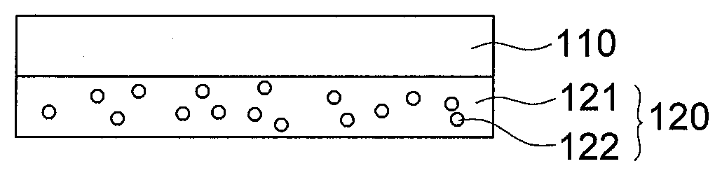
[0047]Hereinafter, the present invention will be described with reference to FIG. 1.
[0048]FIG. 1 is a cross-sectional view illustrating an optical film 101 according to the first embodiment of the present invention.
[0049]The optical film 101 according to the first embodiment of the present invention includes a polarizer 110 and a first adhesive layer 120 may be disposed on one surface of the polarizer 110. The first adhesive layer 120 may have a haze value of 90% or more.
[0050]A polarizing film may be used as the optical film 101 according to the first embodiment of the present invention.
[0051]The polarizer 110 may play a role in preventing external light reflection. A film where dichroic dyes are adsorbed and aligned on a poly vinyl alcohol (PVA)-based resin film may be used as the polarizer 110.
[0052]The PVA-based resins include, for example, a polyvinyl acetate that is a homopolymer of vinyl acetate or a copolymer of the vinyl acetate and another monomer that can be copolymerized...
second embodiment
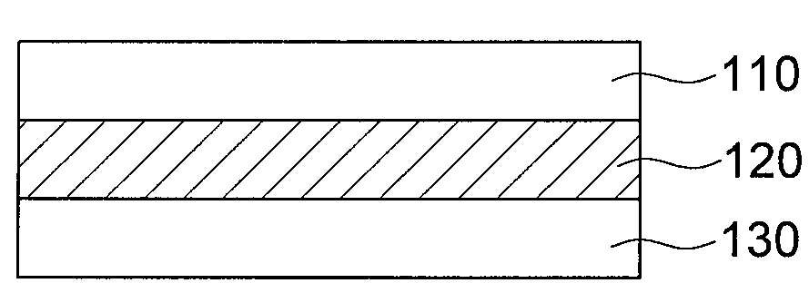
[0115]Hereinafter, the present invention will be described with reference to FIG. 2.
[0116]FIG. 2 is a cross-sectional view illustrating an optical film 102 according to the second embodiment of the present invention. The optical film 102 according to the second embodiment of the present invention includes a polarizer 110, a first adhesive layer 120 disposed on one surface of the polarizer 110, and a phase difference layer 130 disposed on the first adhesive layer 120.
[0117]The phase difference layer 130 may shift a phase of light. The phase difference layer 130 may comprise a phase retardation plate or a phase retardation film. A quarter wave plate (QWP) may be used as the phase difference layer 130 according to the second embodiment of the present invention. However, embodiments of the present invention are not limited thereto, and thus a half wave plate (HWP) may be used as the phase difference layer 130 according to the second embodiment of the present invention.
[0118]The phase di...
third embodiment
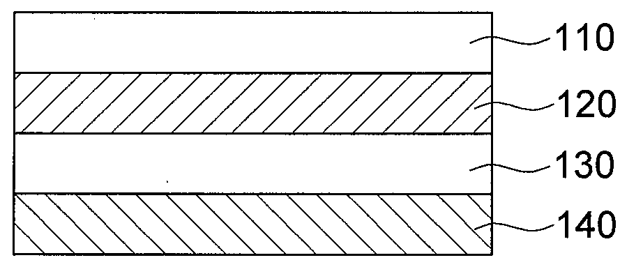
[0124]Hereinafter, the present invention will be described with reference to FIG. 3.
[0125]FIG. 3 is a cross-sectional view illustrating an optical film 103 according to the third embodiment of the present invention. The optical film 103 according to the third embodiment of the present invention includes a polarizer 110, a first adhesive layer 120 disposed on one surface of the polarizer 110, a phase difference layer 130 disposed on the first adhesive layer 120, and a second adhesive layer 140 disposed on the phase difference layer 130.
[0126]A repeated description on the polarizer 130, the first adhesive layer 120, and the phase difference layer 130, as described in the first and second embodiments, will not be provided here.
[0127]The second adhesive layer 140 is configured to attach the optical film 130 to the display device. A haze value of the second adhesive layer 140 is not particularly limited. The second adhesive layer 140 may have the haze value of 90% or more or less than 90...
PUM
 Abstract
Description
Claims
Application Information