
Liquid crystal display

A liquid crystal display and liquid crystal technology, applied in static indicators, instruments, nonlinear optics, etc., can solve the problems of increased transmittance and decreased contrast

Active Publication Date: 2009-04-15
SAMSUNG DISPLAY CO LTD
View PDF0 Cites 0 Cited by
  • Summary
  • Abstract
  • Description
  • Claims
  • Application Information

AI Technical Summary

Problems solved by technology

In the storage swing method, the luminance and side visibility characteristics are improved as the voltage change increases; however, when the voltage change of the storage electrode increases, the transmittance in the black luminance range increases undesirably, and thus leads to a sharp contrast ratio reduce

Method used


Image

  • Liquid crystal display
  • Liquid crystal display
  • Liquid crystal display

Examples


Embodiment Construction

[0028] It will be understood that when an element or layer is referred to as being "on," "connected to," or "coupled to" another element or layer, it can be directly on, connected to, or directly on the other element or layer. To or coupled to other elements or layers, or intervening elements or layers may be present. In contrast, when an element is referred to as being “directly on,” “directly connected to” or “directly coupled to” another element or layer, there are no intervening elements or layers present. Throughout the specification, the same reference numerals refer to the same elements. As used herein, the term "and / or" includes any and all combinations of one or more of the associated listed items.

[0029] It will be understood that, although the terms first, second, etc. may be used herein to describe various elements, components, regions, layers and / or sections, these elements, components, regions, layers and / or sections should not be limited by these terms. Thes...


PUM


Abstract

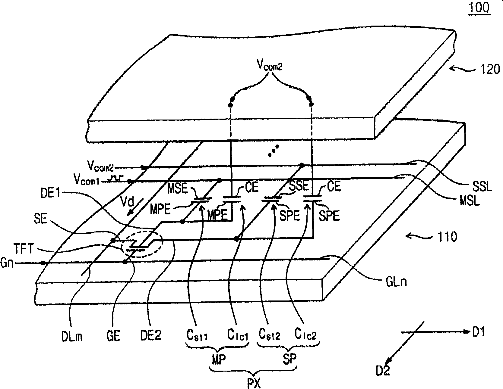
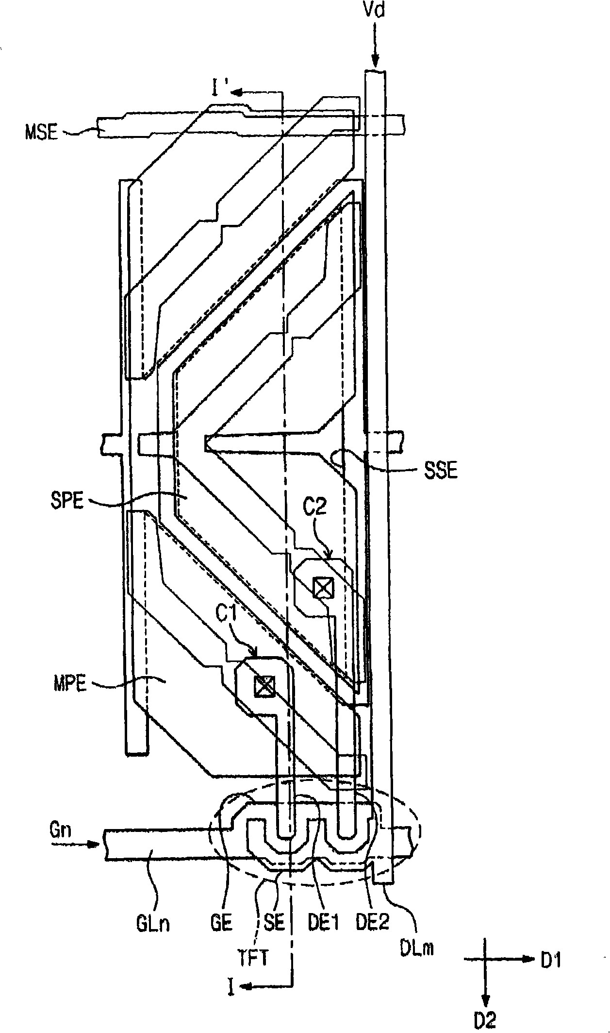
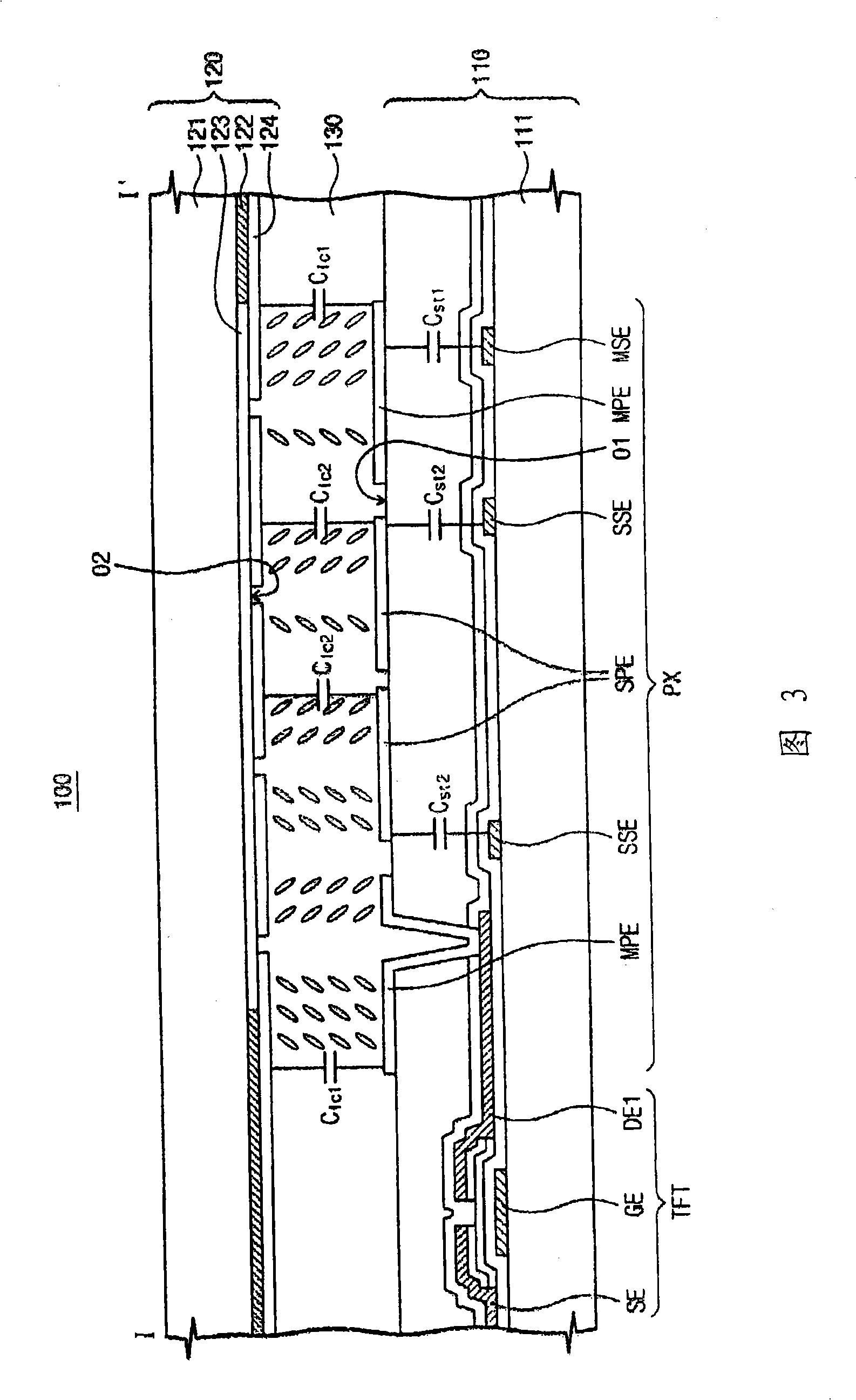
Teh invnetion provides a liquid crystal display and a method for improving a side visibility of the liquid crystal display. In a liquid crystal display, an image-defining data voltage is simultaneously applied to a main pixel electrode (MPE) and an electrically isolatable sub pixel electrode (SPE) to thereby respectively define a main pixel voltage and a sub pixel voltage. The MPE defines one plate of a first capacitor whose other plate receives a first common voltage whose voltage level can be varied after the image-defining data voltage is applied. Thus the main pixel voltage is shifted up or shifted down according to the voltage variation of the first common voltage. The SPE defines one plate of a second capacitor whose other plate receives a second common voltage. By causing the main pixel voltage to be of greater absolute amplitude than the sub pixel voltage, a side visibility of the liquid crystal display can be enhanced.

Description

[0001] Cross References to Related Applications [0002] This application claims priority from Korean Patent Application No. 2007-103180 filed on October 12, 2007, the disclosure of which is hereby incorporated by reference in its entirety. technical field [0003] The present disclosure relates to liquid crystal displays (LCDs). More particularly, the present disclosure relates to a liquid crystal display capable of realizing a wide viewing angle. Background technique [0004] Recently, in order to improve the narrow viewing angle of conventional liquid crystal display devices, various driving methods for liquid crystal display devices have been developed, including patterned vertical alignment (PVA: patterned vertical alignment) mode, multi-quadrant vertical alignment (MVA) mode, and Super Patterned Vertical Alignment (S-PVA) mode. [0005] An LCD device using the S-PVA mode typically includes a pixel region each having two sub-pixels, and each of the two sub-pixels incl...

Claims


Application Information

Patent Timeline
IPC IPC(8): G02F1/1362G09G3/36
CPCG02F2001/134345G09G2300/0443G09G2320/028G09G2320/0238G09G2300/0491G02F1/1393G09G3/3651G09G3/3614G02F1/134345G02F1/133G02F1/1343
Inventor 金勋柳在镇刘惠兰
Owner SAMSUNG DISPLAY CO LTD
Learn More