Light emitting device with blue light LED and phosphor components

a light-emitting device and led-phosphor technology, applied in the field of light-emitting diodes, can solve the problems of complex drive circuits, inability to generate white light of the desired tone, and inability to achieve the desired tone, so as to improve light-emitting efficiency and ensure long life. the effect of high efficiency

Inactive Publication Date: 2006-04-11
NICHIA CORP
View PDF122 Cites 241 Cited by
  • Summary
  • Abstract
  • Description
  • Claims
  • Application Information

AI Technical Summary

Benefits of technology

[0014]Thus, an object of the present invention is to solve the problems described above and provide a light emitting device which experiences only extremely low degrees of deterioration in emission light intensity, light emission efficiency and color shift over a long time of use with high luminance.

Problems solved by technology

When generating white light with such an arrangement, there has been such a problem that white light of the desired tone cannot be generated due to variations in the tone, luminance and other factors of the light emitting component.
Also when the light emitting components are made of different materials, electric power required for driving differs from one light emitting diode to another, making it necessary to apply different voltages different light emitting components, which leads to complex drive circuit.
Moreover, because the light emitting components are semiconductor light emitting components, color tone is subject to variation due to the difference in temperature characteristics, chronological changes and operating environment, or unevenness in color may be caused due to failure in uniformly mixing the light emitted by the light emitting components.
Thus light emitting diodes are effective as light emitting devices for generating individual colors, although a satisfactory light source capable of emitting white light by using light emitting components has not been obtained so far.
However, conventional light emitting diodes have such problems as deterioration of the fluorescent material leading to color tone deviation and darkening of the fluorescent material resulting in lowered efficiency of extracting light.
Especially when a light emitting component made of a semiconductor having a high energy band gap is used to improve the conversion efficiency of the fluorescent material (that is, energy of light emitted by the semiconductor is increased and number of photons having energies above a threshold which can be absorbed by the fluorescent material increases, resulting in more light being absorbed), or the quantity of fluorescent material consumption is decreased (that is, the fluorescent material is irradiated with relatively higher energy), light energy absorbed by the fluorescent material inevitably increases resulting in more significant degradation of the fluorescent material.
Use of the light emitting component with higher intensity of light emission for an extended period of time causes further more significant degradation of the fluorescent material.
Further, some fluorescent materials are subject to accelerated deterioration due to combination of moisture entered from the outside or introduced during the production process, the light and heat transmitted from the light emitting component.
When it comes to an organic dye of ionic property, direct current electric field in the vicinity of the chip may cause electrophoresis, resulting in a change in the color tone.

Method used


Image

  • Light emitting device with blue light LED and phosphor components
  • Light emitting device with blue light LED and phosphor components
  • Light emitting device with blue light LED and phosphor components

Examples


embodiment 1

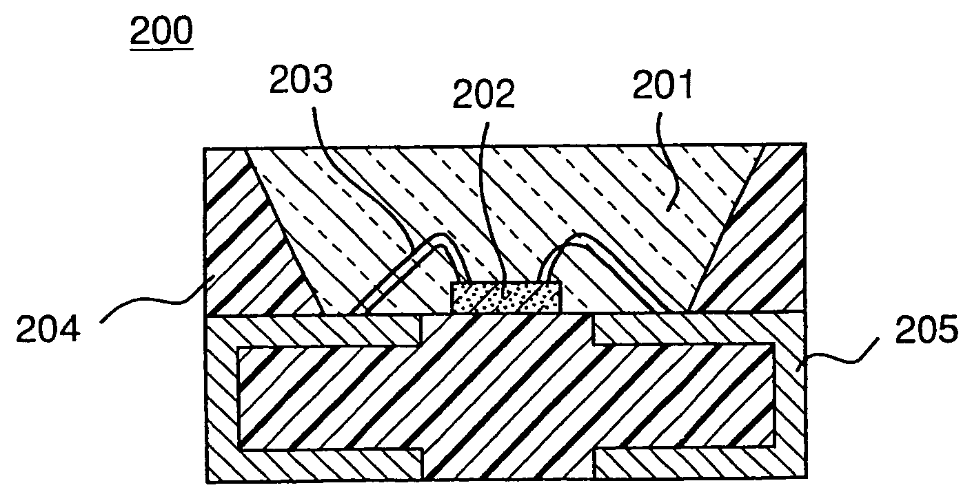
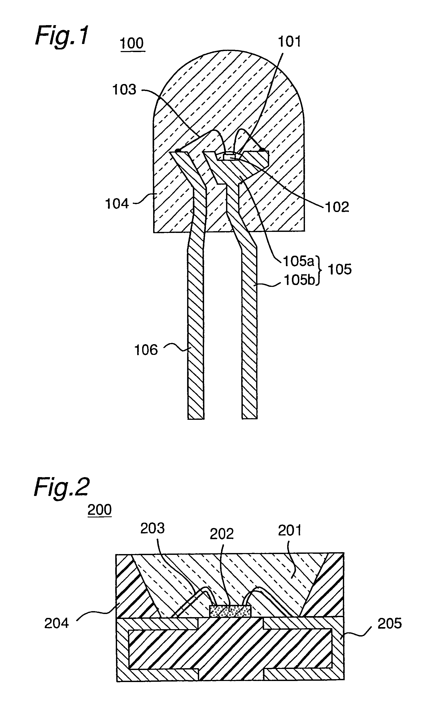
[0100]The light emitting diode of the first embodiment of the present invention employs a gallium nitride compound semiconductor element which has high-energy band gap in the light emitting layer and is capable of emitting blue light, and a garnet phosphor activated with cerium in combination. With this configuration, the light emitting diode of the first embodiment can emit white light by blending blue light emitted by the light emitting components 102, 202 and yellow light emitted by the phosphor excited by the blue light. Because the garnet phosphor activated with cerium which is used in the light emitting diode of the first embodiment has light resistance and weatherability, it can emit light with extremely small degrees of color shift and decrease in the luminance of emitted light even when irradiated by very intense light emitted by the light emitting components 102, 202 located in the vicinity over a long period of time. Components of the light emitting diode of the first emb...

embodiment 2

[0136]The light emitting diode of the second embodiment of the present invention is made by using an element provided with gallium nitride compound semiconductor which has high-energy band gap in the light emitting layer as the light emitting component and a fluorescent material including two or more kinds of phosphors of different compositions, or preferably yttrium-aluminum-garnet fluorescent materials activated with cerium as the phosphor. With this configuration, a light emitting diode which allows to give a desired color tone by controlling the contents of the two or more fluorescent materials can be made even when the wavelength of the LED light emitted by the light emitting component deviates from the desired value due to variations in the production process. In this case, emission color of the light emitting diode can be made constantly using a fluorescent material having a relatively short emission wavelength for a light emitting component of a relatively short emission wav...

example 1

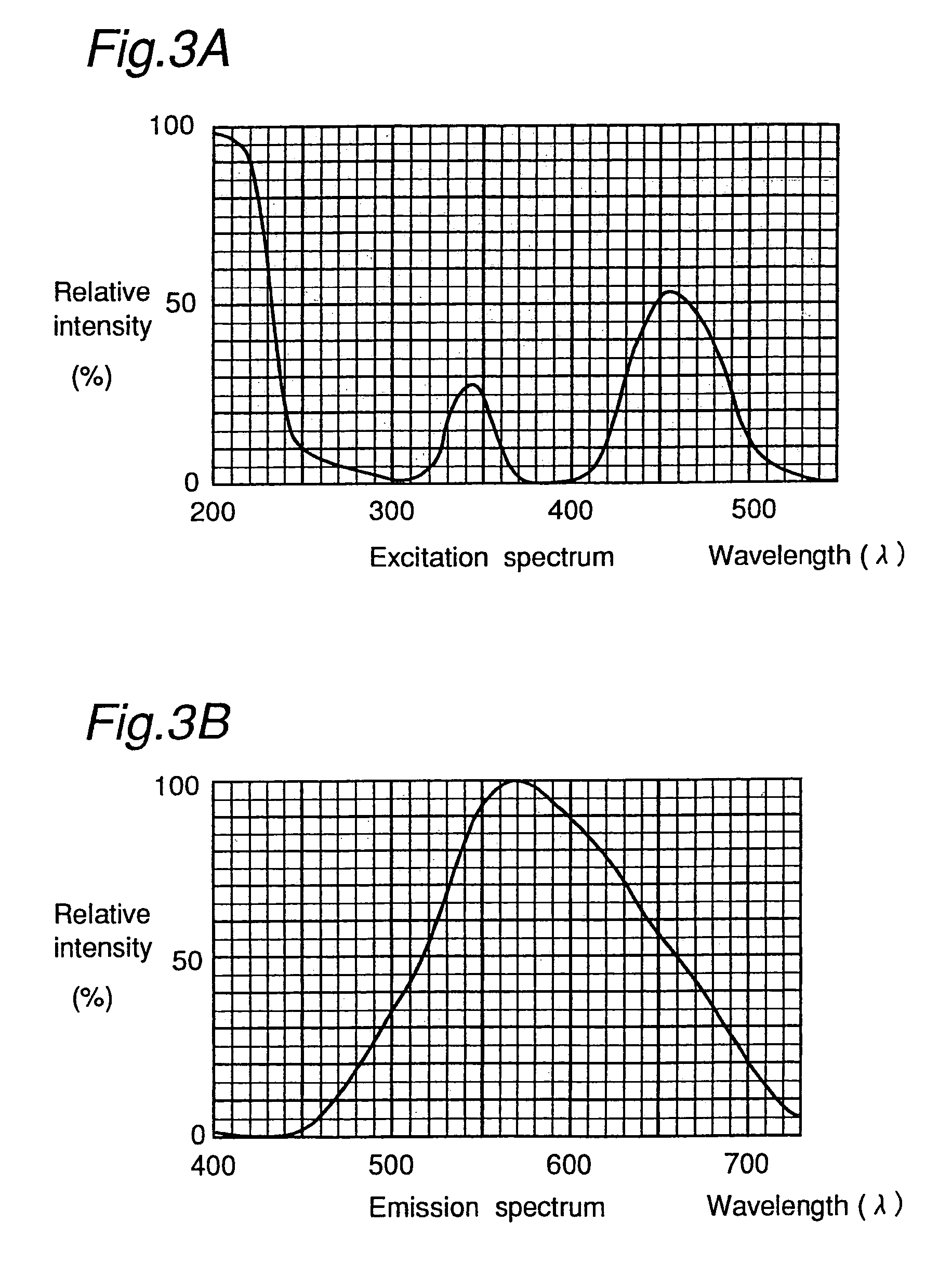
[0164]Example 1 provides a light emitting component having an emission peak at 450 nm and a half width of 30 nm employing a GaInN semiconductor. The light emitting component of the present invention is made by flowing TMG (trimethyl gallium) gas, TMI (trimethyl indium) gas, nitrogen gas and dopant gas together with a carrier gas on a cleaned sapphire substrate and forming a gallium nitride compound semiconductor layer in MOCVD process. A gallium nitride semiconductor having N type conductivity and a gallium nitride semiconductor having P type conductivity are formed by switching SiH4 and Cp2Mg as dopant gas. The LED element of Example 1 has a contact layer which is a gallium nitride semiconductor having N type conductivity, a clad layer which is a gallium nitride aluminum semiconductor having P type conductivity and a contact layer which is a gallium nitride semiconductor having P type conductivity, and formed between the contact layer having N type conductivity and the clad layer h...


PUM

PropertyMeasurementUnit
peak wavelengthaaaaaaaaaa

Abstract

A light emitting device includes a light emitting component having an active layer of a semiconductor and a phosphor capable of absorbing a part of light emitted from the light emitting component and emitting light of wavelength different from that of the absorbed light, wherein the light emitting component is a LED which has an active layer constituting a gallium nitride based semiconductor containing Indium and is capable of emitting a blue color light with a peak wavelength within the range from 420 to 490 nm. The phosphor is a garnet fluorescent material activated with cerium which is capable of absorbing a part of the blue color light and thereby emitting light having a broad emission spectrum with a peak wavelength existing around the range from 510 to 600 nm and a tail continuing into the region from 700 to 750 nm.

Description

[0001]This application is a divisional of application Ser. No. 10 / 609,503 filed on Jul. 1, 2003 (now allowed), which is a divisional of application Ser. No. 09 / 458,024 filed Dec. 10, 1999 (now U.S. Pat. No. 6,614,179 issued Sep. 2, 2003), which is a divisional of application Ser. No. 09 / 300,315 filed on Apr. 28, 1999 (now U.S. Pat. No. 6,069,440 issued May 30, 2000), which is a divisional of application Ser. No. 08 / 902,725 filed on Jul. 29, 1997 (now U.S. Pat. No. 5,998,925 issued Dec. 7, 1999). The entire contents of these applications are hereby incorporated by reference.BACKGROUND OF THE INVENTION[0002]1. Field of the Invention[0003]The present invention relates to a light emitting diode used in LED display, back light source, traffic signal, trailway signal, illuminating switch, indicator, etc. More particularly, it relates to a light emitting device (LED) comprising a phosphor, which converts the wavelength of light emitted by a light emitting component and emits light, and a d...

Claims


Application Information

Patent Timeline
Patent Type & Authority Patents(United States)
IPC IPC(8): H01J1/62H01J1/63H01J1/68C09K11/08C09K11/62C09K11/64C09K11/77C09K11/80F21V8/00F21Y101/02G02B6/00H01L33/06H01L33/28H01L33/32H01L33/34H01L33/36H01L33/44H01L33/50H01L33/54H01L33/56H01L33/60H01L33/62H05B33/00H05B33/12H05B33/14
CPCC09K11/7767G02B6/0023G02B6/0073H01J29/20H01L33/50H01L33/501H01L33/502H05B33/14C09K11/7774H01L2224/45169G02B6/0025G02B6/0051H01L33/504H01L33/56H01L2224/48091H01L2933/0091Y02B20/181H01L2224/45147H01L2224/45124H01L2224/45015H01L24/45H01L2224/73265H01L2924/3025H01L2924/01019H01L2924/01021H01L2924/01067H01L2924/01068H01L2224/45144H01L2924/12041H01L2224/48247H01L2224/48257H01L2224/48465H01L2924/3011H01L2924/15747H01L2924/00014H01L2924/00H01L2924/20751H01L2924/20752H01L2924/20753H01L2924/20754H01L2924/12042H01L2924/12036H01L2924/181H01L2924/00012Y02B20/00
Inventor SHIMIZU, YOSHINORISAKANO, KENSHONOGUCHI, YASUNOBUMORIGUCHI, TOSHIO
Owner NICHIA CORP
Why Eureka
Try Eureka