Balancer mechanism for rotating shaft

a technology of rotating shaft and balancer, which is applied in the direction of presses, press rams, manufacturing tools, etc., can solve the problems of unfavorable manufacturing costs, and achieve the effects of reducing rotary moments, simple shape, and smooth follow-up

Inactive Publication Date: 2006-08-24
PASCAL ENG
View PDF6 Cites 10 Cited by
  • Summary
  • Abstract
  • Description
  • Claims
  • Application Information

AI Technical Summary

Benefits of technology

[0018] The cam member can be made in a simple shape, and the cam follower smoothly follows up the cam member. The balancing rotary moment operates on the rotary shaft via the cam follower and cam member to reduce the rotary moment. Moreover, the magnitude of the rotary moment changes according to the angle of rotation of the rotary shaft, but the position of inputting a force from the cam follower to the cam member, and its direction and magnitude can be properly changed so as to generate a balancing rotary moment having a magnitude corresponding to the magnitude of the rotary moment on the rotary shaft.
[0019] T...

Problems solved by technology

Moreover, the balancer mechanism comprises a simple construction with a ...

Method used


Image

  • Balancer mechanism for rotating shaft
  • Balancer mechanism for rotating shaft
  • Balancer mechanism for rotating shaft

Examples


Embodiment Construction

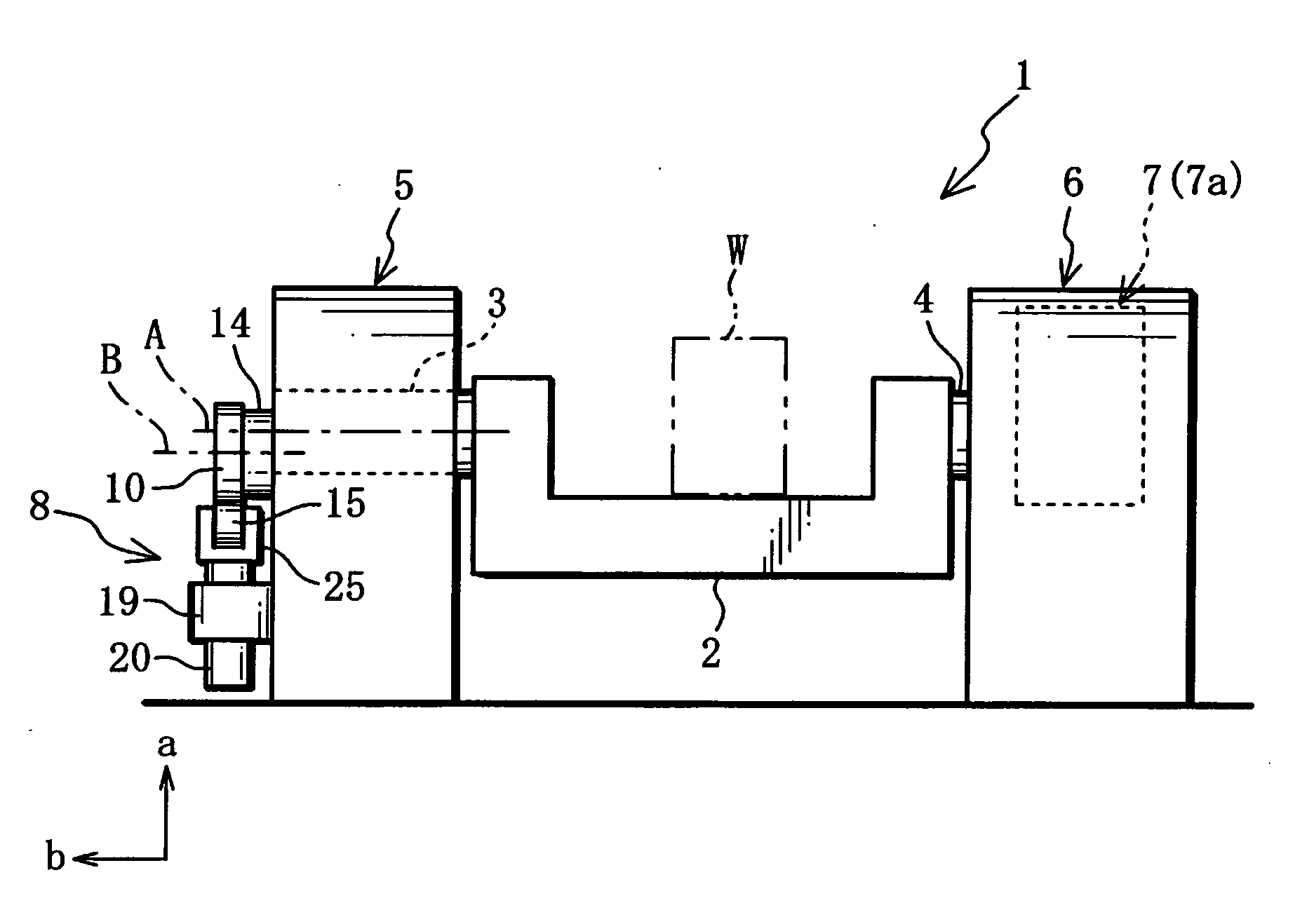
[0028] The embodiment described below is an example of the case of applying a rotary shaft balancer mechanism of the present invention to an indexer in which a work to be machined by a working machine is detachably mounted. Moreover, arrows a and b of FIG. 1 shows, respectively upward and leftward.

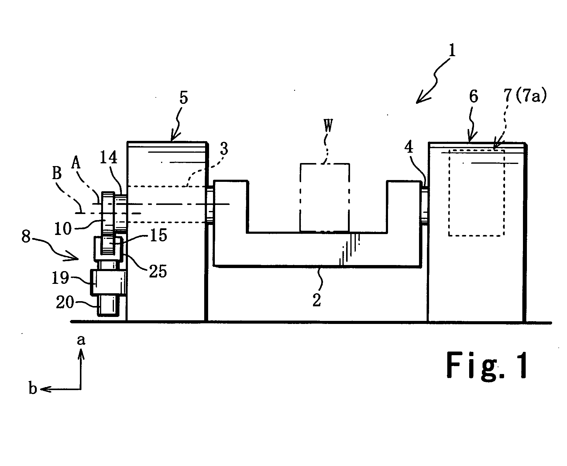
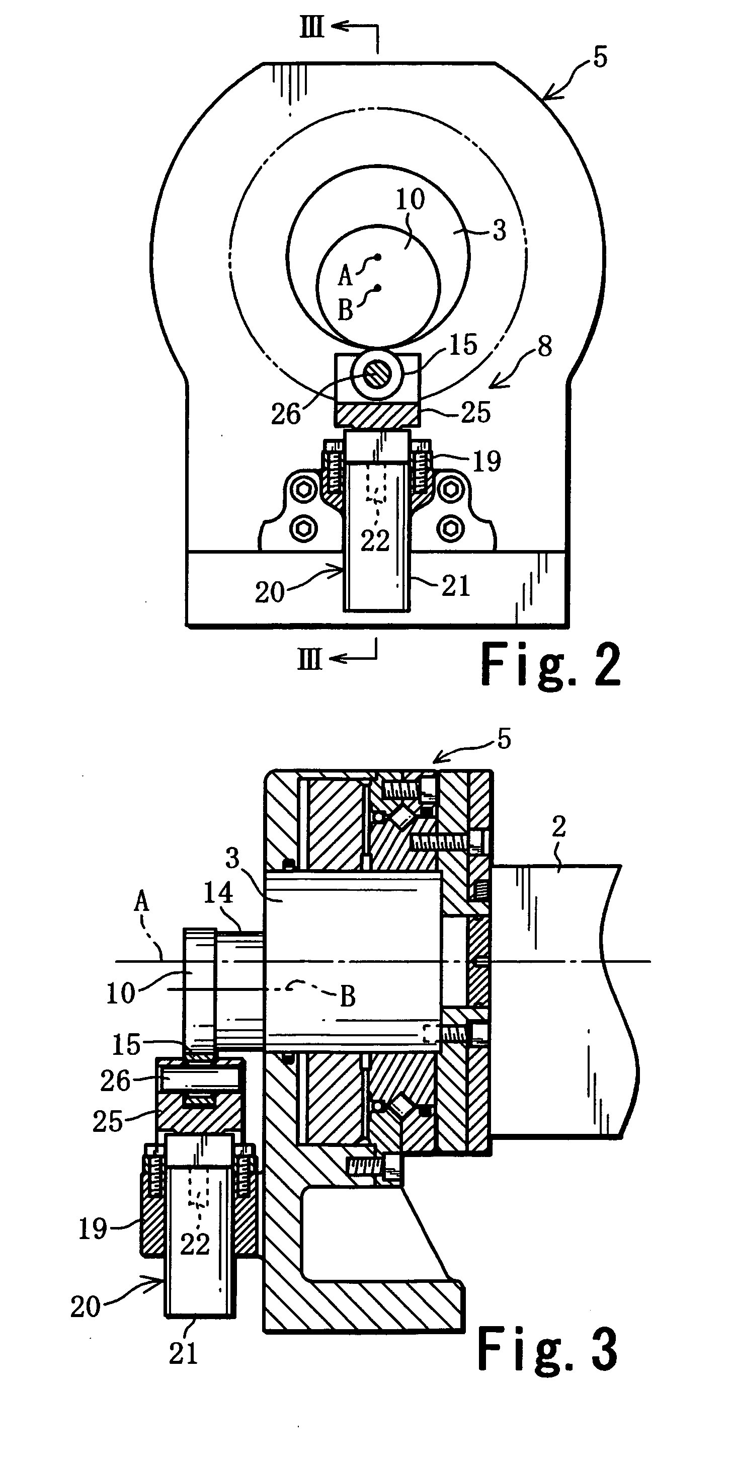
[0029] As shown in FIG. 1, an indexer 1 is provided with a table 2, a pair of rotary shafts 3, 4 fixed to the table 2, a left shaft support mechanism 5 including a shaft support for rotatably supporting the rotary shaft 3, a right shaft support mechanism 6 including a shaft support for rotatably supporting the rotary shaft 4, a rotational drive mechanism 7 having an electric motor 7a for rotationally driving the table 2 and the rotary shafts 3, 4 around the axial center A of the rotary shafts 3, 4, and a rotary shaft balancer mechanism 8 (hereafter referred to as a balancer mechanism 8). Moreover, the construction of the table 2, the rotary shaft 3 and the support mechanism 5 differ more ...


PUM


Abstract

To provide a balancer mechanism where a balancing rotary moment, which offsets at least a part of a rotary moment operating on a rotary shaft, operates on the rotary shaft by a gas spring to reduce the rotary moment simply and reliably.
The balancer mechanism for rotary shaft (8) is provided with a cam member (10) fixed to the left end of rotary shaft (3), a cam follow-up member (15) which makes contact with the cam member (10) to follow it up, and a gas spring (20) comprising a gas spring (20) elastically energizing the cam follow-up member (15) toward the cam member (10) and operates a balancing rotary moment offsetting at least a part of the rotary moment of rotary shaft on the rotary shaft (3) via the cam follow-up member (16) and the cam member (10).

Description

TECHNICAL FIELD [0001] The present invention relates to a balancer mechanism for reducing a rotary moment which acts on a rotary shaft from members supported by the rotary shaft which is rotatably supported by one or more shaft supports. BACKGROUND ART [0002] In an indexer, crank press or robot arm, etc., rotary shafts are rotatably supported on one or more shaft supports and members such as a table, a movable disc, and an arm are supported on the rotary shaft. [0003] For example, in the indexer, a pair of rotary shafts fixed to a table are rotatably supported on a pair of shaft supports, and a driving force is applied by an electric motor to the rotary shaft to rotationally drive the table. [0004] The table is provided with a turn table, rotatable around a shaft perpendicular to the axial center of the rotary shaft and its drive mechanism, a work is detachably mounted on the turn table to machine. [0005] Usually, it is difficult make the center of gravity of the table and the work ...

Claims


Application Information

Patent Timeline
IPC IPC(8): F16F15/22B23Q1/52B23Q11/00B30B1/26B30B15/00F16F15/04F16F15/26
CPCB23Q1/52B23Q11/0021B30B1/26Y10T74/2122F16F15/043F16F15/22F16F15/261B30B15/0064
Inventor MACHIDA, MASAHIROYOTSUBAYASHI, HIROYUKI
Owner PASCAL ENG
Why Eureka
Try Eureka