Liquid crystal display device

a liquid crystal display and display device technology, applied in instruments, cathode-ray tube indicators, light sources, etc., can solve the problems of increasing the time required for stabilizing brightness and chromaticity, and affecting the brightness of the display device. achieve the effect of reducing the time required

Inactive Publication Date: 2006-10-05
NEC DISPLAY SOLUTIONS LTD
View PDF6 Cites 86 Cited by
  • Summary
  • Abstract
  • Description
  • Claims
  • Application Information

AI Technical Summary

Benefits of technology

[0040] It is an object of the present invention to provide a liquid crystal display device employing LEDs as light ...

Problems solved by technology

However, the light sensing circuit used as light detection means has the possibility of causing fluctuations of the electric current output of the photodiodes used for light detection due to temperature changes and also has the possibility of causing fluctuations of the resistance of the resistor used in the amplification circuit for converting the electric current outputs of the photodiodes into voltages, due to temperature changes.
As described above, conventional stabilization/control circuits for L...

Method used


Image

  • Liquid crystal display device
  • Liquid crystal display device
  • Liquid crystal display device

Examples


first embodiment

(A. First Embodiment)

(A-1. Device Configuration)

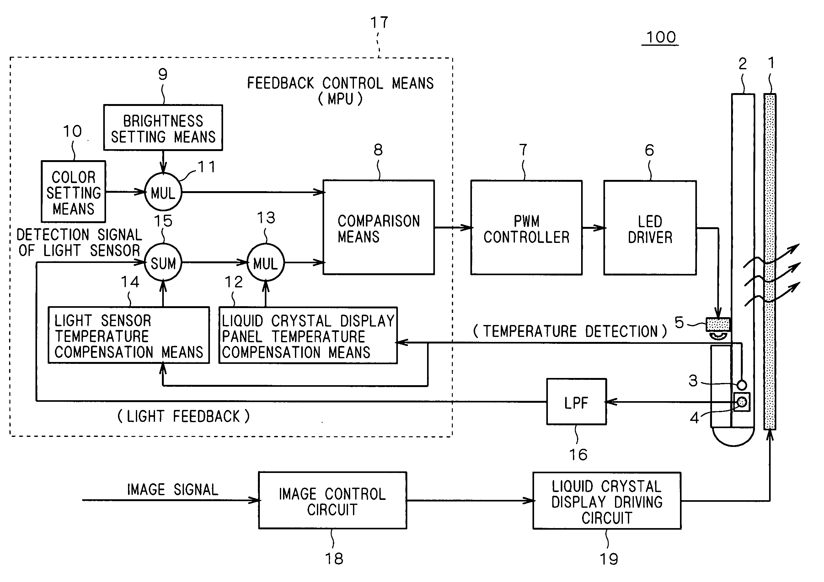
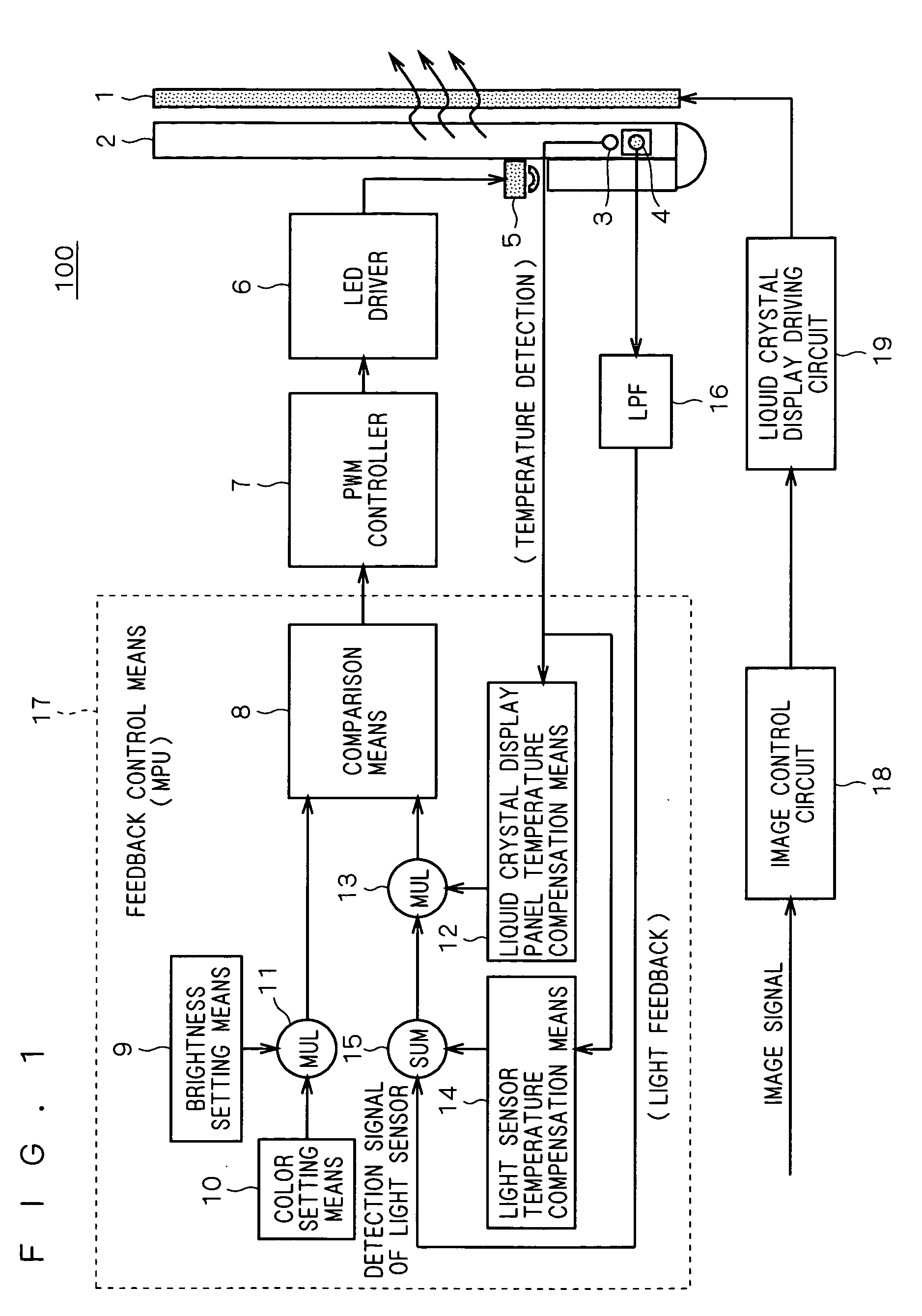
[0056]FIG. 1 is a block diagram illustrating the structure of a liquid crystal display device 100 according to a first embodiment of the present invention.

[0057] The liquid crystal display device 100 illustrated in FIG. 1 is structured such that a feedback control means 17 performs feedback control of a PWM controller 7 and an LED driver 6 on the basis of information about the temperature of a light guide plate 2 and information about the intensities of red light, green light and blue light, which are output from a temperature detection means (temperature sensor IC) 3 and a light detection means (light sensor IC) 4 mounted on the light guide plate 2.

[0058] Namely, the light guide plate 2 constituting a backlight system is mounted to the back surface (the surface opposite from the display surface) of a liquid crystal display (LCD) panel 1. The light guide plate 2 is a member for mixing red (R), green (G) and blue (B) monochromatic l...

second embodiment

(B. Second Embodiment)

(B-1. Device Configuration)

[0160]FIG. 6 is a block diagram illustrating the structure of a liquid crystal display device 200 according to a second embodiment of the present invention. In FIG. 6, like reference characters describe the same components as those of the liquid crystal display device 100 illustrated in FIG. 1 and description thereof will not be repeated.

[0161] The feedback control means 17 for controlling the PWM controller 7 is configured to include a brightness setting means 9, a color setting means 10, a light sensor temperature compensation means 14 for compensating for fluctuations of the output of the light detection means 4 (referred to as a light sensor or a brightness sensor, in some cases) due to the temperature changes, a liquid crystal display panel temperature compensation means 12 for compensating for fluctuations of the spectral transmittance of the liquid crystal display panel due to the temperature changes, a multiplication means ...


PUM


Abstract

The present invention provides a liquid crystal display device capable of shortening the time required for stabilizing the brightness and the chromaticity to the temperature change. The input of an LED driver is connected to the output of a PWM controller, so that the electric power supplied to the respective LED groups of red, green and blue are controlled with a PWM method. A feedback control means for controlling the PWM controller includes a brightness setting means, a color setting means, a multiplication means for receiving the outputs from the brightness setting means and the color setting means, a comparison means fed with the output of the multiplication means at one of the inputs thereof, a light sensor temperature compensation means for compensating for fluctuations of the output of the light detection means due to temperature changes, a liquid crystal display panel temperature compensation means for compensating for fluctuations of the spectral transmittance of the liquid crystal display panel due to temperature changes, an addition means for summing the result of detection by the light detection means and the output of the light sensor temperature compensation means, and a multiplication means for multiplying the output of the addition means by the output of the liquid crystal display panel temperature compensation means.

Description

BACKGROUND OF THE INVENTION [0001] 1. Field of the Invention [0002] The present invention relates to liquid crystal display devices including a backlight and, more particularly, relates to transmitted-light-display type liquid crystal display devices including LEDs (Light Emitting Diodes) as a light source. [0003] 2. Description of the Background Art [0004]FIG. 8 is a block diagram illustrating an LED light source stabilization / control circuit 90 disclosed in Armand Perduijn et al., “43.2: Light Output Feedback Solution for RGB LED Backlight Applications”, “SID2003 CD-ROM”. [0005] The stabilization / control circuit 90 illustrated in FIG. 8 is broadly divided into a color control means 22, a brightness control means 23 and an LED driving duty ratio control means 24. [0006] The color control means 22 is structured to include an addition means 222, an integration means 223, a PWM control block 224, an LED driving / operation detection block 225 and a low-pass filter 226. [0007] The bright...

Claims


Application Information

Patent Timeline
IPC IPC(8): G09G3/36G02F1/133G02F1/13357H05B37/02
CPCG09G3/3406G09G2320/041G09G5/02
Inventor TANIZOE, HIDEKIKIMURA, TAROUENO, HIROSHIKATO, HIROSHI
Owner NEC DISPLAY SOLUTIONS LTD
Why Eureka
Try Eureka