
Device for an adjusting mechanism, said adjusting mechanism and method
a technology of adjusting mechanism and adjusting mechanism, which is applied in the direction of electric devices, seating furniture, electric vehicles, etc., can solve the problems of fitting for this purpose, and achieve the effects of small, lightweight and cost-effective, large, heavy and expensive production, and comparatively low effort for actuation
- Summary
- Abstract
- Description
- Claims
- Application Information
AI Technical Summary
Benefits of technology
Problems solved by technology
Method used
Image

Examples
Embodiment Construction
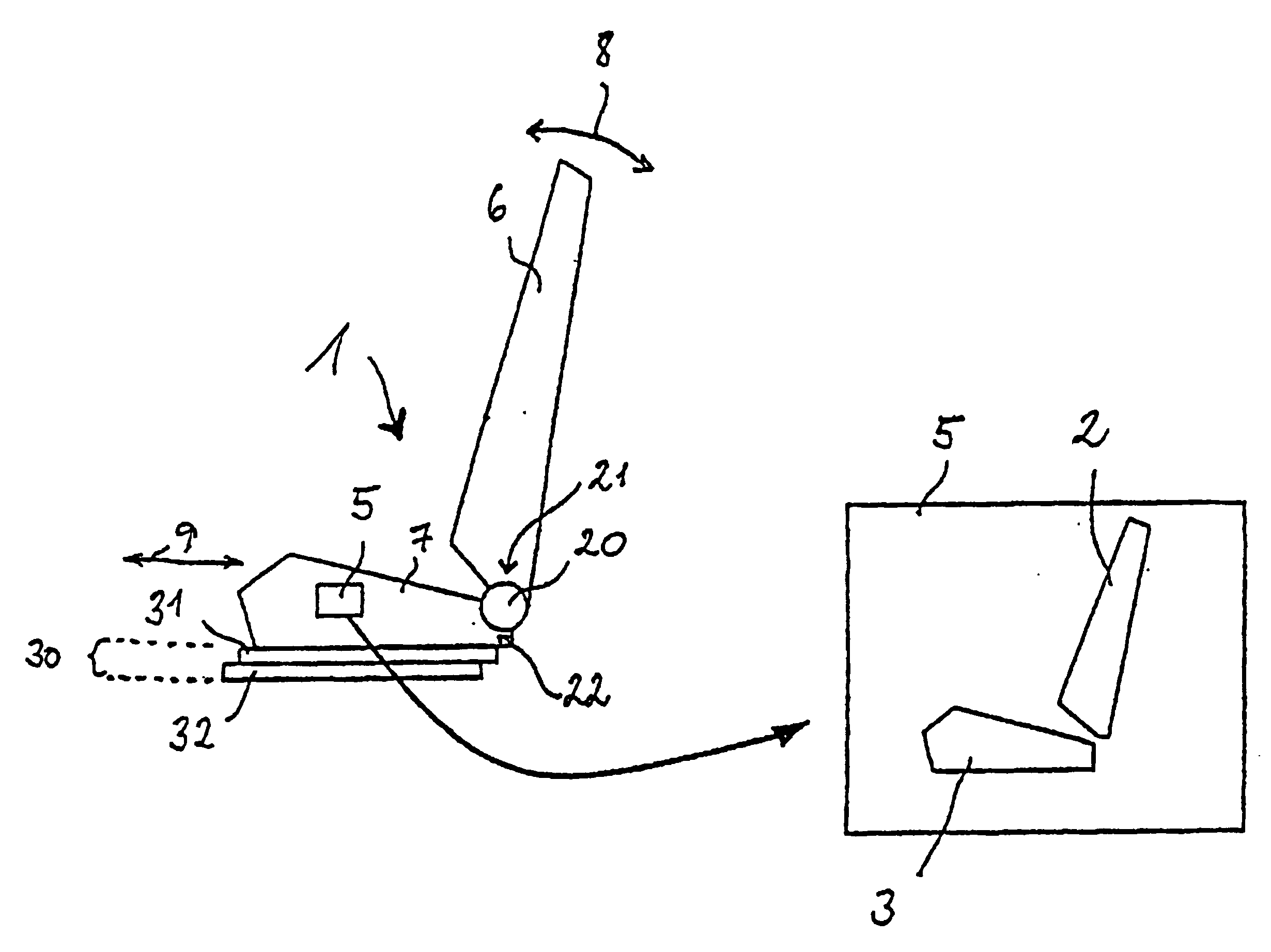
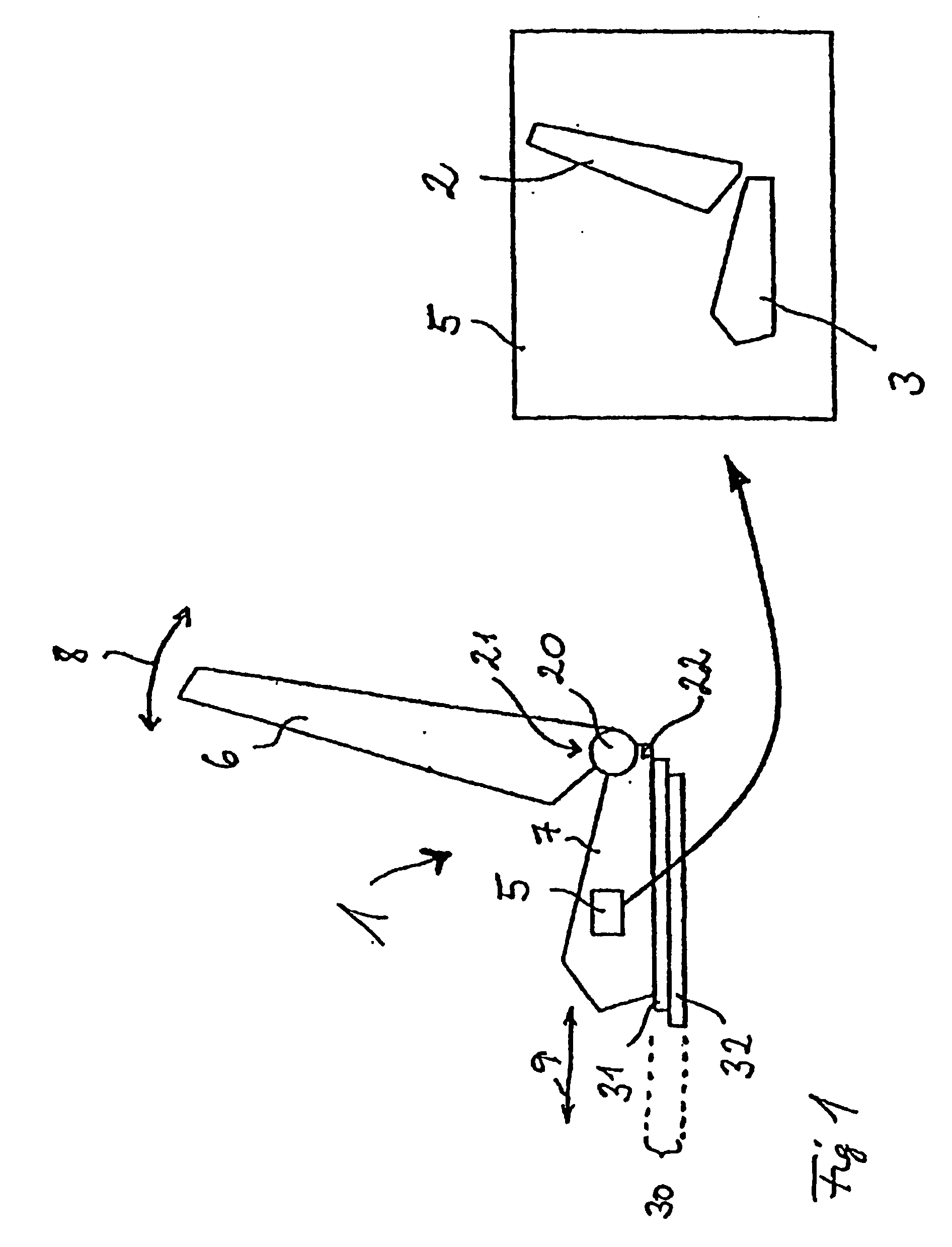
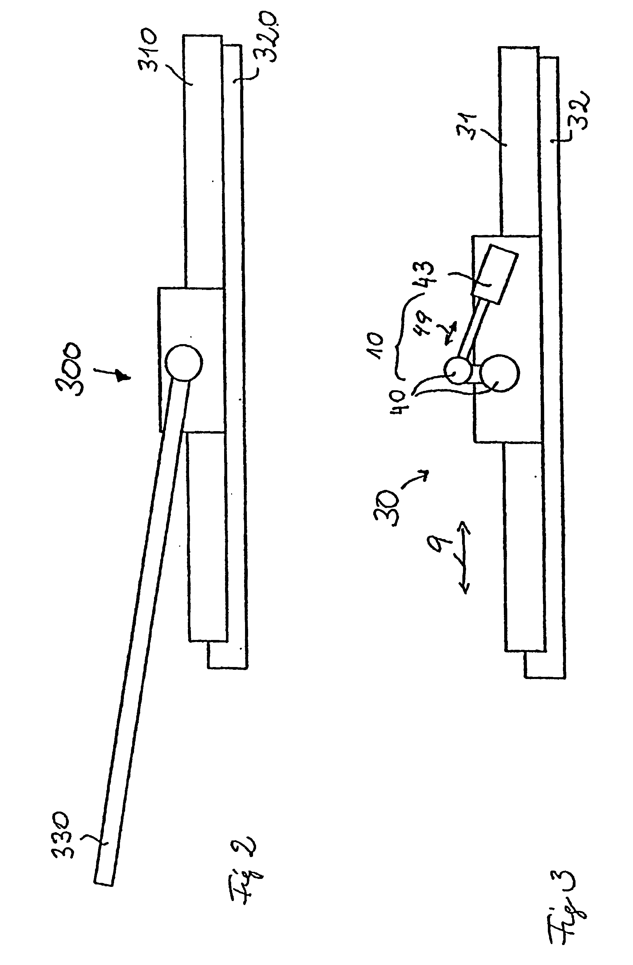
[0033]FIG. 1 illustrates, in the left-hand part of the figure, a component 1 with a first adjusting mechanism 30 and a second adjusting mechanism 20 and an operating unit 5 (illustrated on an enlarged scale). The component 1 is provided in particular as a seat 1 of a motor vehicle (not shown), but may also be any other desired component of a motor vehicle. The first adjusting mechanism 30 comprises a first part 31 and a second part 32 which can be moved in a translatory manner with respect to each other. The second adjusting mechanism 20 comprises a first part 21 (merely indicated by means of an arrow and the reference number 21) and a second part 22 (merely indicated by means of an arrow and the reference number 22), the parts 21, 22 of the second adjusting mechanism 20 being movable in a rotary manner with respect to each other. By means of a respective blocking means (not illustrated in FIG. 1) for the two adjusting mechanisms 20, 30, the parts 31, 32 of the first adjusting mecha...
PUM
 Abstract
Description
Claims
Application Information