Vehicle seat adjusting mechanism

a technology of adjusting mechanism and seat, which is applied in the direction of seat furniture, electric vehicles, electric devices, etc., can solve the problems of fit for this purpose, and achieve the effects of small, lightweight and cost-effective, large, heavy and expensive production, and comparatively low effort for actuation

Inactive Publication Date: 2010-02-23
DZHONSON KONTROLZ GMBKH
View PDF10 Cites 14 Cited by
  • Summary
  • Abstract
  • Description
  • Claims
  • Application Information

AI Technical Summary

Benefits of technology

[0005]The present invention, in one embodiment, relates to a device for blocking and for releasing an adjusting mechanism, in which the adjustment of the adjusting mechanism itself is not provided automatically, for example electrically or pneumatically, but rather in which the setting of the adjusting mechanism from a first possible setting to a second possible setting is carried out manually. Only the unlocking or the release of the adjusting mechanism is undertaken—triggered by the actuation of an actuating element—in an automated manner, for example pneumatically or electrically, by means of an unlocking actuator. As a result, the device according to the invention can be produced to be small, lightweight and cost-effective, for example because a large-sized, heavy and expensive motor for automated adjustment is not necessary. According to one embodiment of the invention there is a device for blocking and for releasing an adjusting mechanism, in which the adjusting mechanism is provided at least in two settings, the device having a blocking means which can be brought at least into a blocking position and into a release position relative to the adjusting mechanism, an adjustment of the adjusting mechanism from its first setting into its second setting being provided only when the blocking means is in its release position, a change in position of the blocking means from its blocking position into its release position being provided by means of an electric and / or pneumatic unlocking actuator. The device of the present invention has the advantage that the unlocking actuator does not have to be actuated manually. This makes it unnecessary to position the actuating element for the unlocking actuator at a location at which a user of the adjusting mechanism firstly cannot comfortably bring about an unlocking of the adjusting mechanism, or makes it unnecessary to provide complicated mechanical assisting means which, although they permit an unlocking of the adjusting mechanism at a comfortably accessible location, are large, heavy and expensive to produce and to fit for this purpose. Furthermore, it is advantageously possible according to the invention to provide an actuating element in such a manner that the effort for its actuation is comparatively low. As a result, even users who are physically relatively weak can operate the adjusting mechanism in a simple and safe manner. In another embodiment of the present invention, it is advantageously possible to provide an operation of the actuating element in which great forces do not have to be applied either for adjusting the adjusting mechanism or for actuating the unlocking actuator.
[0006]In one embodiment of the present invention there is a device for unlocking and for maintaining the unlocking of an adjusting mechanism, it being possible for the adjusting mechanism to be set in a first setting position and in a second setting position, the adjusting mechanism having a reversibly releasable and blockable blocking means, an adjustment of the adjusting mechanism from its first setting position into its second setting position being provided only when the blocking means is released, the release of the blocking means furthermore being provided by means of an electric and / or pneumatic unlocking actuator, an activation of the unlocking actuator being provided at the beginning of a setting period and a deactivation of the unlocking actuator being provided at the end of the setting period, and the device comprising detection means for detecting the end of the setting period or detection means of this type being assigned to the device. This enables a particularly user-friendly operation of the adjusting mechanism. Furthermore, a multiplicity of different setting situations or a multiplicity of possible termination criteria of the setting or adjusting operation of the adjusting mechanism is possible.

Problems solved by technology

This makes it unnecessary to position the actuating element for the unlocking actuator at a location at which a user of the adjusting mechanism firstly cannot comfortably bring about an unlocking of the adjusting mechanism, or makes it unnecessary to provide complicated mechanical assisting means which, although they permit an unlocking of the adjusting mechanism at a comfortably accessible location, are large, heavy and expensive to produce and to fit for this purpose.

Method used


Image

  • Vehicle seat adjusting mechanism
  • Vehicle seat adjusting mechanism
  • Vehicle seat adjusting mechanism

Examples


Embodiment Construction

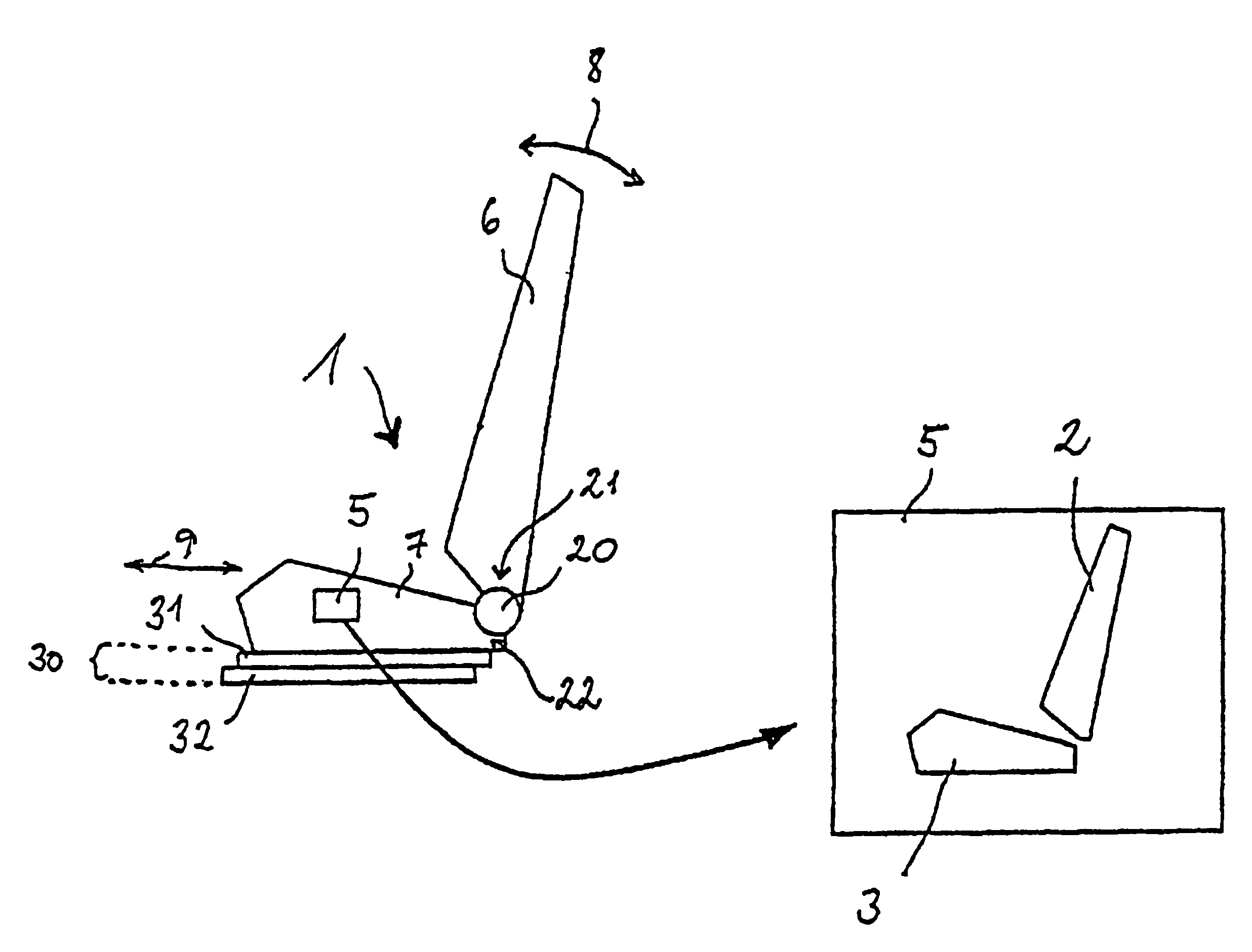
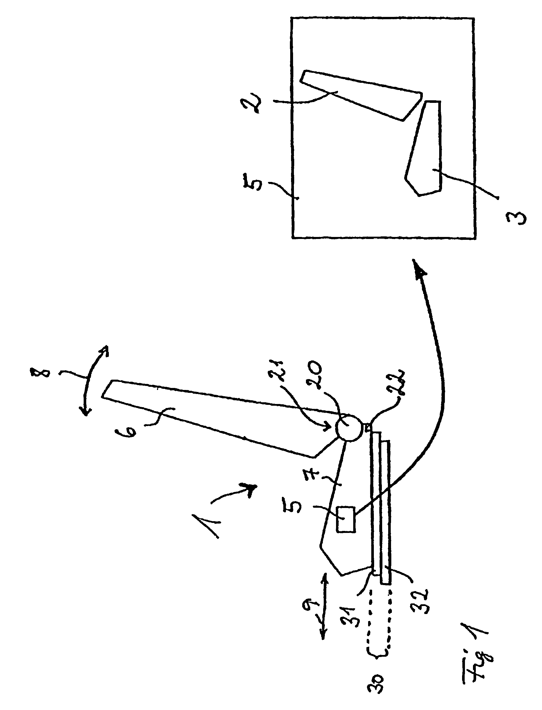
[0033]FIG. 1 illustrates, in the left-hand part of the figure, a component 1 with a first adjusting mechanism 30 and a second adjusting mechanism 20 and an operating unit 5 (illustrated on an enlarged scale). The component 1 is provided in particular as a seat 1 of a motor vehicle (not shown), but may also be any other desired component of a motor vehicle. The first adjusting mechanism 30 comprises a first part 31 and a second part 32 which can be moved in a translatory manner with respect to each other. The second adjusting mechanism 20 comprises a first part 21 (merely indicated by means of an arrow and the reference number 21) and a second part 22 (merely indicated by means of an arrow and the reference number 22), the parts 21, 22 of the second adjusting mechanism 20 being movable in a rotary manner with respect to each other. By means of a respective blocking means (not illustrated in FIG. 1) for the two adjusting mechanisms 20, 30, the parts 31, 32 of the first adjusting mecha...


PUM


Abstract

A device for blocking and for releasing an adjusting mechanism having at least two parts which are movable relative to each other is disclosed. The device comprises a blocker configured to be brought at least into a blocking position and a release position relative to the adjusting mechanism. The device further comprises an actuator for changing the position of the blocker between the blocking position and the release position.

Description

CROSS-REFERENCE TO RELATED PATENT APPLICATIONS[0001]Germany Priority Application DE 103 21 426.7, filed May 12, 2003 including the specification, drawings, claims and abstract, is incorporated herein by reference in its entirety. Germany Priority Application DE 103 41 866.0, filed Sep. 9, 2003 including the specification, drawings, claims and abstract, is incorporated herein by reference in its entirety. This application is a National Stage of US Application PCT / EP2004 / 004920, filed Jul. 5, 2004, incorporated herein by reference in its entirety.FIELD OF THE INVENTION[0002]The invention relates generally to a device for blocking and for releasing an adjusting mechanism for use in a vehicle seat. In particular the invention relates to for components of motor vehicles—such as, for example, seats, sliding roofs and more of the like which can be set mechanically into a plurality of positions, for operating elements or actuating elements which permit the mechanical setting of the componen...

Claims


Application Information

Patent Timeline
Patent Type & Authority Patents(United States)
IPC IPC(8): A47C1/00B60N2/02B60N2/06B60N2/90B60N2/08B60N2/22
CPCB60N2/0228B60N2/0244B60N2/0252B60N2/06B60N2/0881B60N2/22B60N2/442B60N2/919
Inventor BUDWEG, MARIOPELLENZ, WOLFGANGCZINKI, ALEXANDERHOGE, RALFBOUDINOT, RICHARDSZABLEWSKI, PIOTR
Owner DZHONSON KONTROLZ GMBKH
Why Eureka
Try Eureka