Method for the restoration of damaged areal components

a technology for aircraft engines and compressor blades, which is applied in the direction of machines/engines, manufacturing tools, mechanical equipment, etc., can solve the problems of reducing affecting the service life of compressor blades, and prone to damage, so as to achieve low rework effort

Inactive Publication Date: 2008-11-11
ROLLS ROYCE DEUT LTD & CO KG
View PDF44 Cites 33 Cited by
  • Summary
  • Abstract
  • Description
  • Claims
  • Application Information

AI Technical Summary

Benefits of technology

[0005]In a broad aspect, the present invention provides a method and an apparatus for the repair of worn or damaged solid compressor blades, in particular, blisk-technology compressor blades, by build-up welding enabling three-dimensionally shaped blades to be restored on each edge and in any required length with low rework effort.

Problems solved by technology

The compressor blades of aircraft engines are subject to considerable erosion in the area of the tip and—if the content of sand in the air is high—also in the area from the tip to the trailing edge.
In addition, the leading edge of the compressor blades, in particular, is prone to damage by larger objects (by small stones, for example).
Damaged or worn blades can be replaced by new ones if they are separately manufactured and detachably mounted to the compressor disk.
This already costly method can, however, not be applied to compressor wheels made in blisk technology where the disk forms an integral part with the blades.
In fact, the possibilities for the repair of the compressor blades are limited.
Laser powder build-up welding in a mold is, however, disadvantageous in that the blade can only be restored in a confined tip area of a few millimeters, this being due to recesses limiting the depth of input of the laser beam and the powder in the mold and, further, the complex, three-dimensional blade shape impeding the removal of a longer mold from the repaired blade upon build-up welding.

Method used


Image

  • Method for the restoration of damaged areal components
  • Method for the restoration of damaged areal components
  • Method for the restoration of damaged areal components

Examples


Embodiment Construction

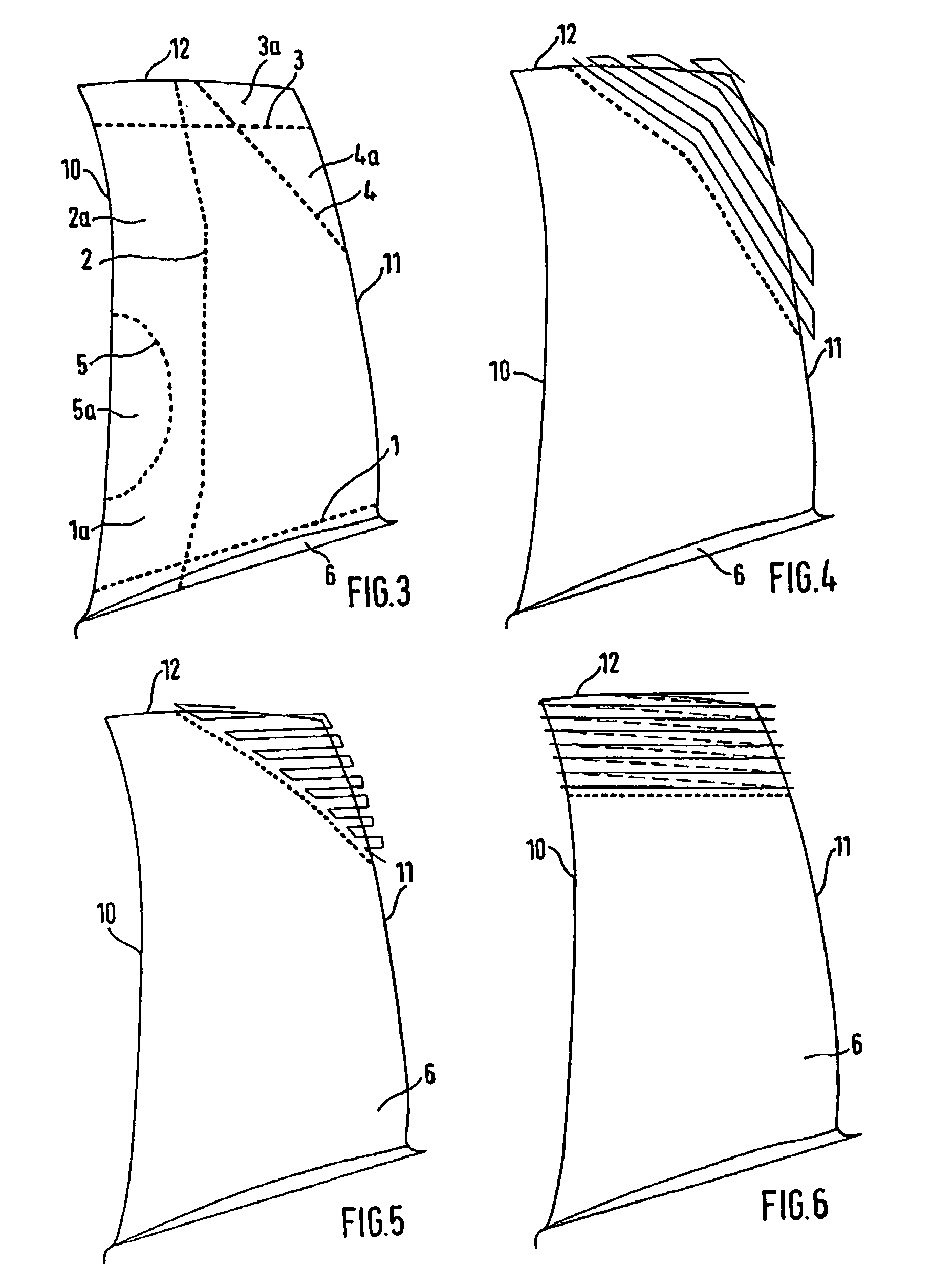
[0019]In accordance with FIG. 3, the following primary cases of blade damage and restoration apply:[0020]1. The blade is unusable over its entire length and will, therefore, be separated at the blade root along line 1 and restored from this sectional plane.[0021]2. The blade is deformed at the leading edge. The damaged portion will be separated along line 2 and the blade restored from this sectional plane.[0022]3. The tip of the blade is, as usual, eroded by the effect of flow and will be repaired by build-up welding from line 3.[0023]4. The blade is worn in a corner area at the tip and trailing edge by an exceptionally high content of airborne particles and will be repaired from line 4.[0024]5. The blade is damaged by a foreign object in a limited area on the leading edge. The damaged area will be cut out along line 5 and the blade restored along this sectional plane.

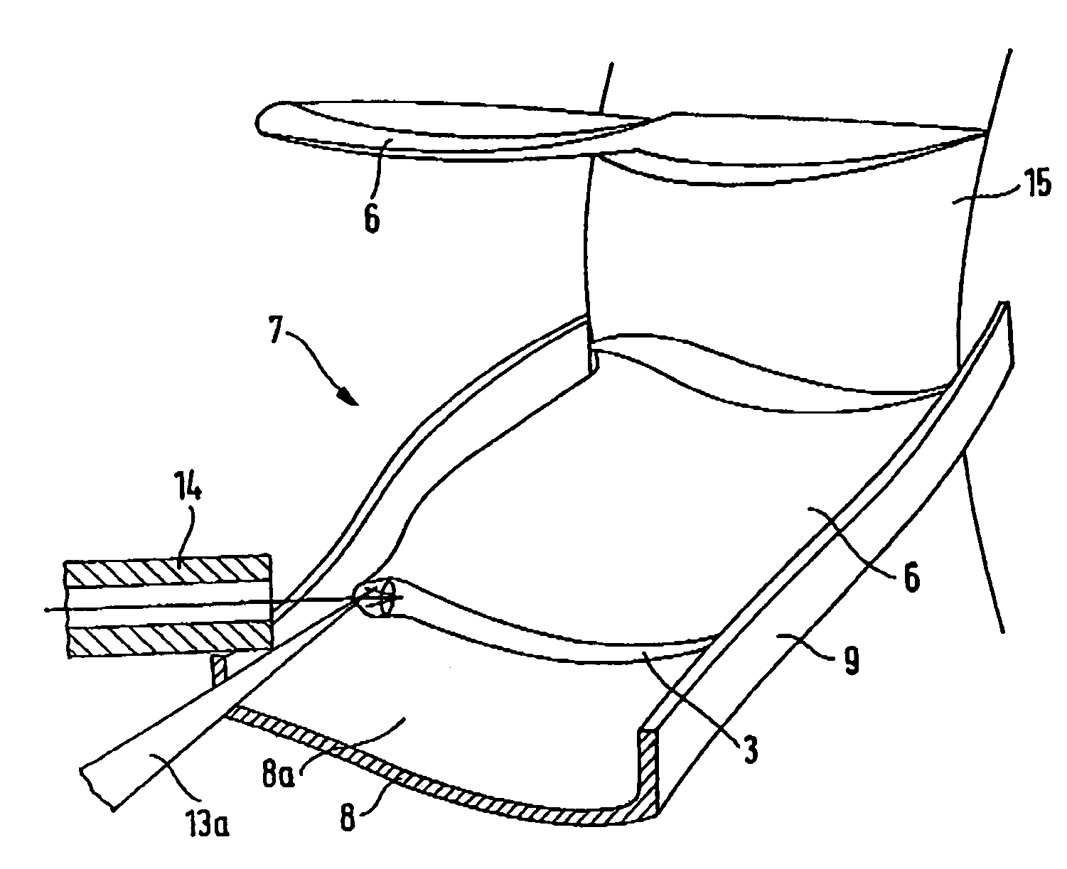
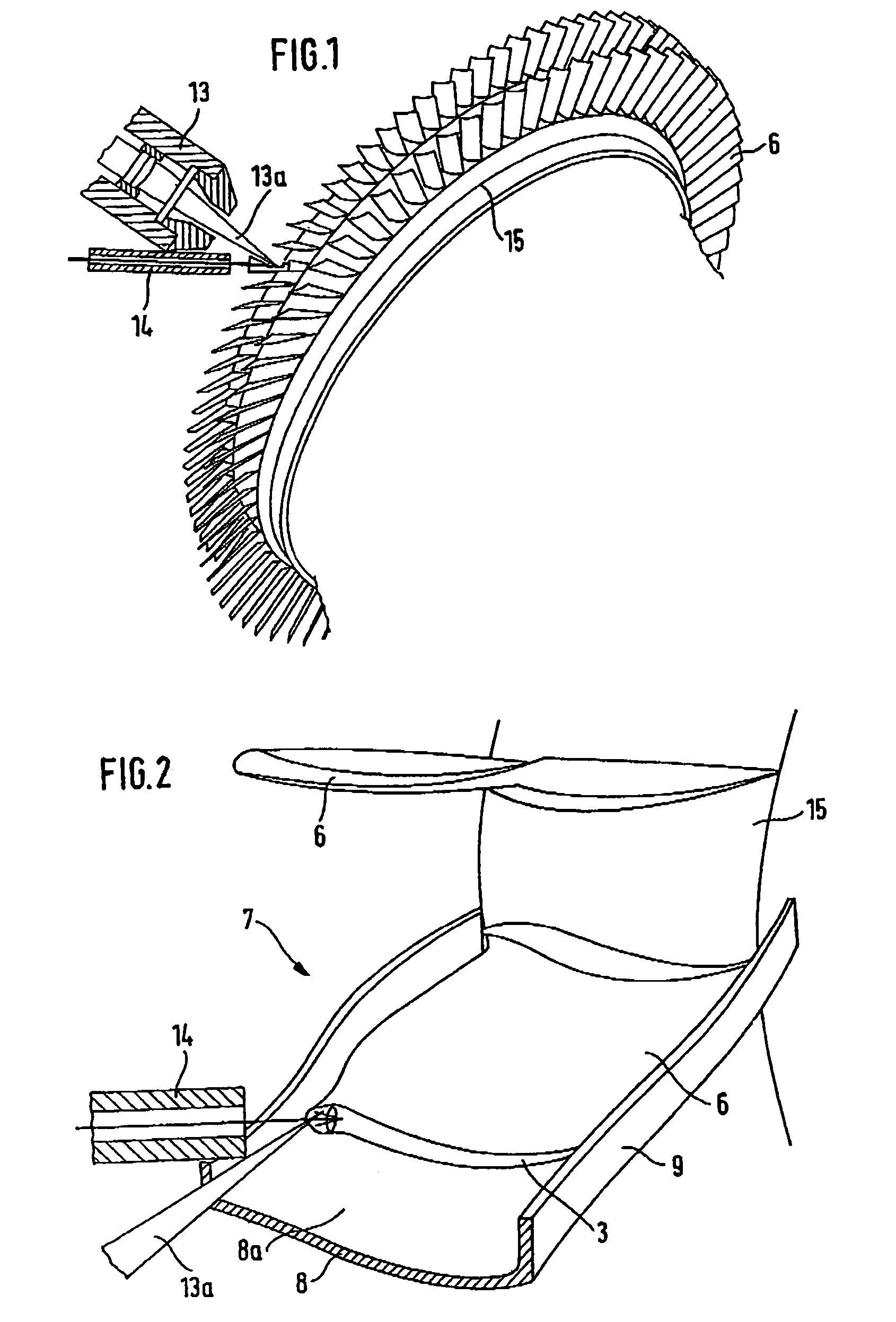
[0025]Upon removal of the damaged portion 1a, 2a, 3a, 4a or 5a of the compressor blade 6 at the respective dotted li...


PUM

PropertyMeasurementUnit
pressureaaaaaaaaaa
thicknessaaaaaaaaaa
sizeaaaaaaaaaa

Abstract

Repair of compressor blades (6) of aircraft engines is performed by build-up welding against an essentially horizontal backing (8) whose surface shape is the exact negative of the respective bottom side of the blade to be repaired. With low rework effort, the blades of blisks can, in the installed state, be repaired or fully restored at any point with high quality upon removal of the damaged portion.

Description

[0001]This application claims priority to German Patent Application DE10316966.0 filed Apr. 12, 2003, the entirety of which is incorporated by reference herein.BACKGROUND OF THE INVENTION[0002]This invention relates to a method for the restoration of worn or otherwise damaged components by build-up welding, in particular, solid, three-dimensional compressor blades of aircraft engines.[0003]The compressor blades of aircraft engines are subject to considerable erosion in the area of the tip and—if the content of sand in the air is high—also in the area from the tip to the trailing edge. In addition, the leading edge of the compressor blades, in particular, is prone to damage by larger objects (by small stones, for example). Damaged or worn blades can be replaced by new ones if they are separately manufactured and detachably mounted to the compressor disk. This already costly method can, however, not be applied to compressor wheels made in blisk technology where the disk forms an integ...

Claims


Application Information

Patent Timeline
Patent Type & Authority Patents(United States)
IPC IPC(8): B23K26/34B23P6/00F01D5/00F01D5/34
CPCB23P6/007F01D5/005F01D5/34B23K26/345Y10T29/49318F05D2230/80F05D2230/232F05D2230/30B23K26/342
Inventor MIELKE, RAINER
Owner ROLLS ROYCE DEUT LTD & CO KG
Why Eureka
Try Eureka