Surveillance apparatus having a radar sensor

a technology of radar sensor and surveillance apparatus, which is applied in the field of surveillance systems, can solve the problems of optical surveillance camera image impairment, optical system attack, etc., and achieve the effect of low technical effor

Active Publication Date: 2016-06-30
SONY CORP
View PDF6 Cites 32 Cited by
  • Summary
  • Abstract
  • Description
  • Claims
  • Application Information

AI Technical Summary

Benefits of technology

[0011]It is an object of the present disclosure to provide a surveillance apparatus and a corresponding surveillance method which overcome the above-mentioned drawbacks, in particular to determine a position of an object in the near field of a radar sensor with low technical effort. It is a further object to provide a corresponding computer program and a non-transitory computer-readable recording medium for implementing said method.

Problems solved by technology

Optical security cameras and surveying systems show good performance during regular operating conditions, however, the optical surveillance cameras are prawn to visual impairments.
The images of the optical surveillance cameras can be impaired by smoke, dust, fog, fire and dirt on the camera system and the like.
An optical surveillance camera is also vulnerable to attacks of the optical system, for example paint from a spray attack, stickers glued to the optical system, card-board or paper obstruction in the field of view, or simply a photograph that pretends that the expected scene is monitored.
Furthermore, the optical system can be attacked by laser pointers, by blinding the camera or by mechanical repositioning of the optical system.
Since radar sensors work at lower frequencies than optical systems, a compact radar system cannot achieve a high resolution to identify targets in the field of view using conventional beam forming methods.
In the related art many methods are known for determining and estimating a target direction in a field of view of a radar sensor system using maximum likelihood estimation algorithms or MUSIC algorithms, however, the known methods for estimating a position of a target in the field of view, in particular the MUSIC algorithm have a high accuracy for objects in the far field which emit uncorrelated electromagnetic signals, however, the performance of the known algorithms degrades when the signal correlation increases and the objects are disposed close to the radar sensors.
By means of introducing the defined distance, the plane wave assumption of the far field can be replaced by the sphere wave assumption of the near field without introducing an additional parameter which would lead to a complicated algorithm and to a complicated determination of the direction of the position of the object.

Method used


Image

  • Surveillance apparatus having a radar sensor
  • Surveillance apparatus having a radar sensor
  • Surveillance apparatus having a radar sensor

Examples


Embodiment Construction

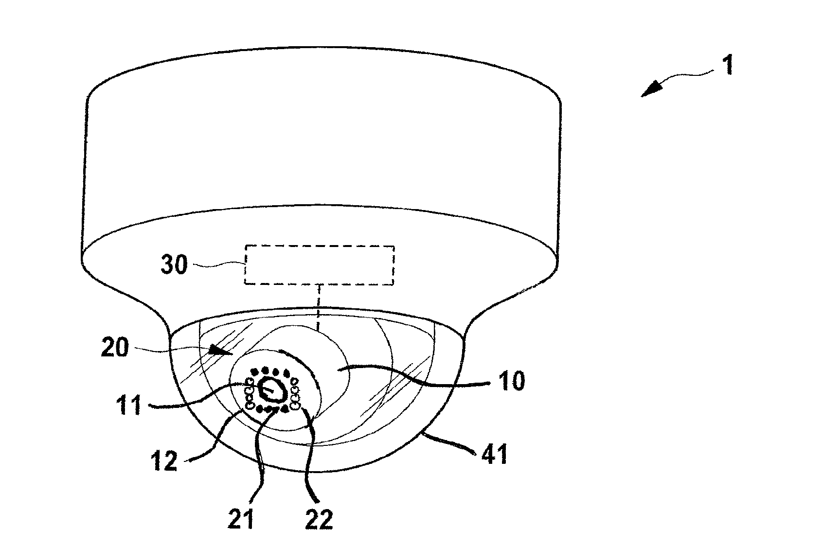
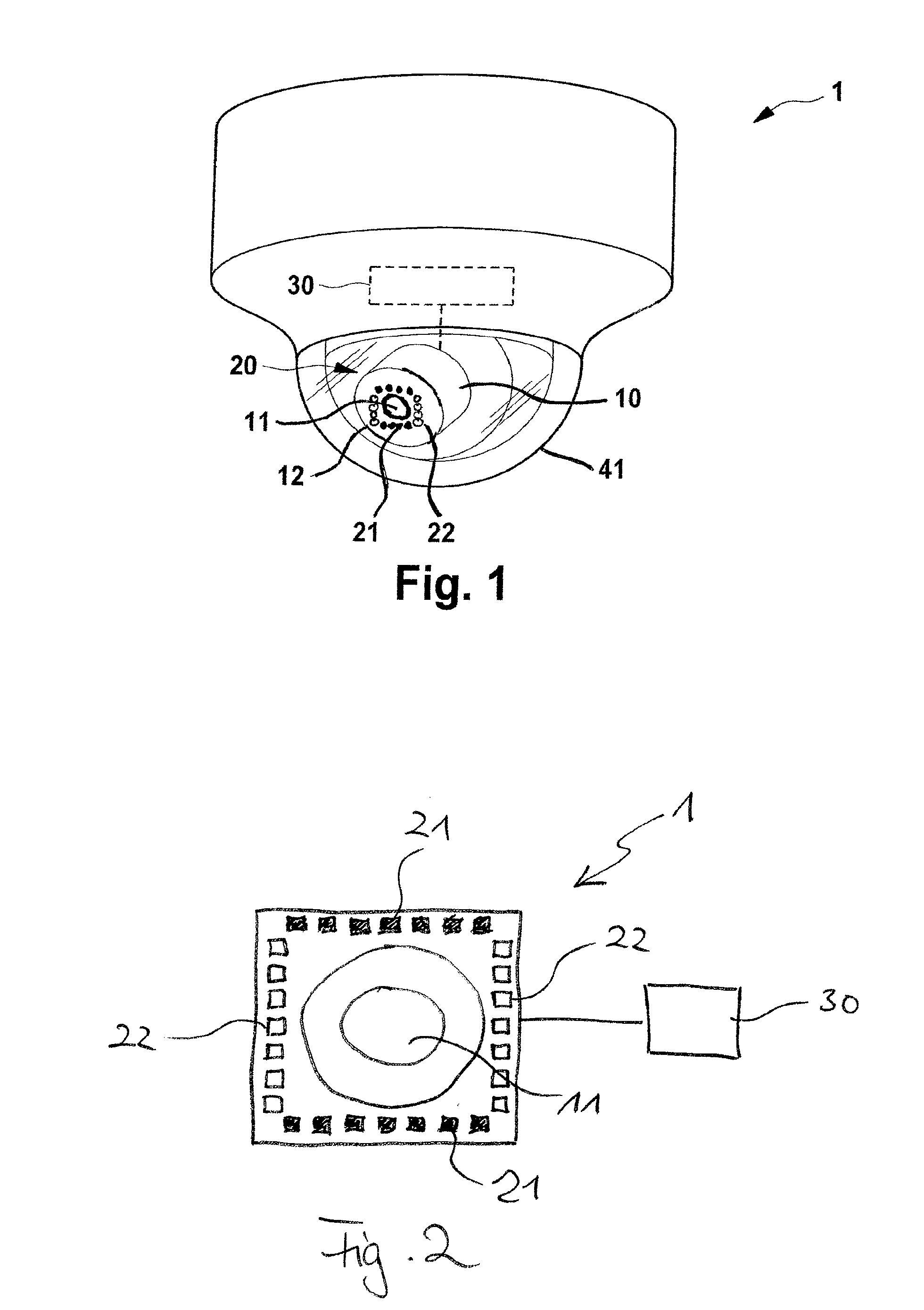
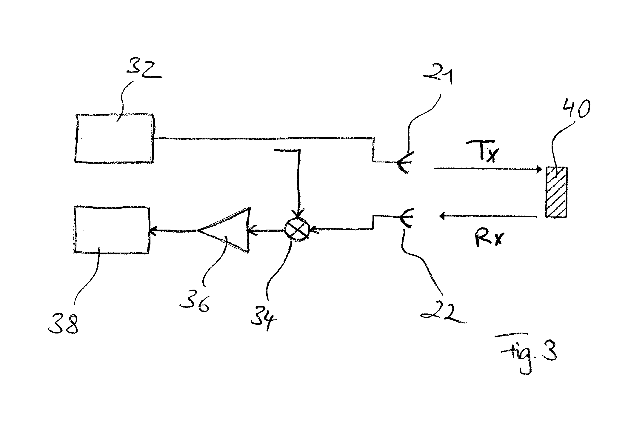
[0034]Referring now to the drawings, wherein like reference numerals designate identical or corresponding parts throughout the several views, FIG. 1 shows a first embodiment of a surveillance apparatus 1 according to the present disclosure. The surveillance apparatus 1 comprises an optical camera 10 configured to capture images based on received light, wherein the optical camera 10 comprises a camera aperture 11. The surveillance apparatus 1 further comprises a radar sensor 20 having one or more (here eight) transmitting antennas 21 (indicated by full circles) configured to emit electromagnetic radiation and one or more (here eight) receiving antennas 22 (indicated by empty cycles) configured to receive electromagnetic radiation. In this embodiment the antennas 21, 22 are arranged on the frame 12 of the camera 10 around the camera aperture 11. Due to their arrangement the cameras 21, 22 form a virtual antenna array. In a more general embodiment, the surveillance system 1 merely comp...


PUM


Abstract

A surveillance apparatus for determining a position of an object in a field of view, comprising a radar sensor having at least on transmitting antenna configured to transmit electromagnetic radiation and a plurality of receiving antennas configured to receive electromagnetic radiation, wherein the receiving antennas form a virtual antenna array, and a processing unit connected to the radar sensor to receive signals from the receiving antennas corresponding to the received electromagnetic radiation, wherein the processing unit is configured to determine a correlation matrix on the basis of the received signals, and wherein the processing unit is configured to determine a direction of a position of the object in the field of view with respect to the radar sensor on the basis of the correlation matrix for a defined distance of the object from the radar sensor.

Description

[0001]The present application claims priority to European Patent Application 14200460.5 filed by the European Patent Office on 29 Dec. 2014, the entire contents of which being incorporated herein by reference.BACKGROUND[0002]1. Field of the Disclosure[0003]The present disclosure relates to the field of surveillance systems for safety and security applications. A surveillance apparatus for determining a position of an object in a field of view having a radar sensor and a corresponding surveillance method are disclosed. Application scenarios include burglar, thefts or intruder alarm as well as monitoring public and private areas, inside or outside.[0004]2. Description of Related Art[0005]Optical surveillance cameras are used in many public places like train stations, stadiums, subways etc. to prevent crimes or to identify criminals after they committed a crime. Optical surveillance cameras are widely used in the retail stores for video surveillance. Other important applications are sa...

Claims


Application Information

Patent Timeline
Patent Type & Authority Applications(United States)
IPC IPC(8): G01S13/42G01S13/86G06T7/00H04N7/18G06K9/00
CPCG01S13/42H04N7/183G06T2207/30232G06T7/004G01S13/867G06K9/00771G01S7/03G01S13/886G01S2013/0245G08B13/1618G08B13/19617
Inventor WANG, QI
Owner SONY CORP
Why Eureka
Try Eureka