Universal voltage converter and inductive power coupling

a voltage converter and inductive power technology, applied in the direction of dc-ac conversion without reversal, process and machine control, instruments, etc., can solve the problems of inability to make a robust power connection, numerous problems with such coupling arrangements, and inability to provide ac and dc line operation compatibility with a simple control circuitry. , to achieve the effect of small size, low technical effort and improved efficiency

Active Publication Date: 2019-07-23
KONINKLIJKE PHILIPS ELECTRONICS NV
View PDF28 Cites 0 Cited by
  • Summary
  • Abstract
  • Description
  • Claims
  • Application Information

AI Technical Summary

Benefits of technology

[0008]It is an object of the present invention to provide a voltage converter having a small size, an increased efficiency and which is compatible with AC and DC line operations and different frequencies with low technical effort.
[0009]It is a further object of the invention to provide a robust inductive power coupling that eliminates the requirement that an inductive coupling member that is connected to a power source is continuously electrically live.
[0010]It is a further object of the invention to provide a robust inductive power coupling that significantly reduces the stray electromagnetic field around the inductive coupling.

Problems solved by technology

However, the conventional transformers operating at the AC line frequency of 50 / 60 Hz are necessarily bigger than those transformers operating at higher frequencies due to the physical nature of inductive coupling.
None of the conventional voltage transformers provide AC and DC line operation compatibility with a simple control circuitry.
However, numerous problems exist with such coupling arrangements.
In harsh environments, it is difficult to make a robust power connection where a reliable high volume of power can be transferred between the coupling members.
Water, salt, oil or other contaminants provide major contact problems for the exposed-contact type of coupling.
Watertight sealing is often difficult or even impossible in such situations.
In addition, a liquid environment would prevent the coupling from being opened or closed, due to the risk of contamination, power leakage or a short-circuit.
However, these systems include numerous flaws and safety concerns that prevent their widespread acceptance.

Method used


Image

  • Universal voltage converter and inductive power coupling
  • Universal voltage converter and inductive power coupling
  • Universal voltage converter and inductive power coupling

Examples


Embodiment Construction

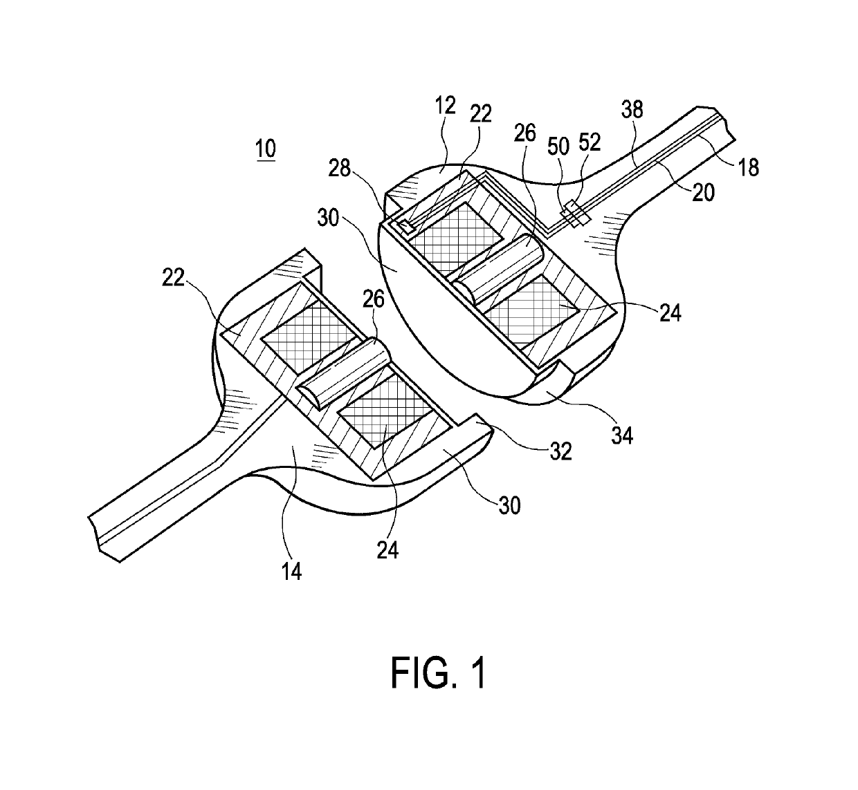
[0048]FIG. 1 illustrates a sectional perspective view of an inductive power coupling 10 comprising a first coupling member 12 which is connectable to a power supply 16 via a set of primary conductors 18, 20. A second coupling member 14 is couplable to the first coupling member 12 for inductive power transfer. Both the first and second coupling members 12, 14 include a set of conductive coils 24, and a permanent magnet 26. The magnets 26 are for drawing the first and second coupling members 12, 14 together magnetically, i.e. for coupling the first and second coupling members 12, 14.

[0049]Both the first coupling member 12 and the second coupling member 14 include a sealing member 30 which envelopes each of the coupling members 12, 14 separately.

[0050]An automatic power switch 28 is connected to the primary conductors 18, 20 from the power supply 16 inside the first coupling member 12. The power switch 28 is actuated when the second coupling member 14 is coupled to the first coupling m...


PUM


Abstract

The present invention relates to a Voltage converter (100) for converting an input voltage (V10) to an output voltage (V20) comprising an input circuitry (102) for receiving the input voltage (V10) from a power supply (112), wherein the input circuitry includes chopper means (110) for chopping a voltage (V12) derived from the input voltage (V10) at a chopper frequency to a chopped voltage (V14), an inductive transformer unit (106) for transforming the chopped voltage (V14) to a chopped AC voltage (V16), and an output circuitry (104) for converting the chopped AC voltage (V16) of the inductive transformer unit (106) to the output voltage (V20) having a lower frequency than the chopper frequency.

Description

CROSS-REFERENCE TO PRIOR APPLICATIONS[0001]This application is the U.S. National Phase application under 35 U.S.C. § 371 of International Application No. PCT / IB2012 / 054021, filed on Aug. 7, 2012, which claims the benefit of, U.S. Provisional Patent Application No. 61 / 540,713, filed on Sep. 29, 2011, and U.S. Provisional Patent Application No. 61 / 522,719, filed on Aug. 12, 2011. These applications are hereby incorporated by reference herein.FIELD OF THE INVENTION[0002]The present invention relates to a voltage converter for converting an input voltage to an output voltage and an inductive power coupling for the inductive transfer of electric power.BACKGROUND OF THE INVENTION[0003]Numerous 50 / 60 Hz line transformers and switch mode transformers operating in the kHz range are state of the art. However, the conventional transformers operating at the AC line frequency of 50 / 60 Hz are necessarily bigger than those transformers operating at higher frequencies due to the physical nature of ...

Claims


Application Information

Patent Timeline
Patent Type & Authority Patents(United States)
IPC IPC(8): H02J50/12H02M7/44H02M5/04H02M5/42H02M3/24H05B41/24H05B33/08H02M7/48H02J5/00H02M5/45H02J50/80H02J50/90H02J50/70H04B5/00H02J11/00H02M1/00H05B44/00
CPCH04B5/0037H02J50/12H02J50/70H02J50/80H02J50/90H02M3/24H02M5/04H02M5/42H02M5/45H02M7/44H02M7/4807H05B33/0815H05B41/24H02J5/005H02M2001/007H02J11/00H05B45/39H05B45/382H02M1/007
Inventor JANSEN, GERARDUS LUCIEN MATHILDUSSAHIN NOMALER, FUNDANEMLIOGLU, CANVAN DER VOORT, RONALD HANS
Owner KONINKLIJKE PHILIPS ELECTRONICS NV
Why Eureka
Try Eureka