

Method and an Array for Magnetizing a Magnetizable Object
- Summary
- Abstract
- Description
- Claims
- Application Information
AI Technical Summary
Benefits of technology
Problems solved by technology
Method used
Image

Examples
first embodiment
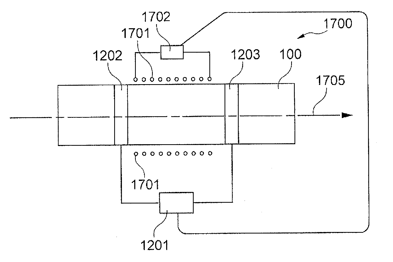
[0445]In the following, referring to FIG. 75, an array 800 for adjusting a magnetization of a shaft 100 according to the invention will be described.
[0446]The array 800 for adjusting a magnetization of a magnetizable shaft 100 comprises the shaft 100 having a magnetized portion (not shown) extending along a part of the shaft 100. In the scenario of FIG. 75, the magnetized portion extends along the part of the shaft 100 extending between a first degaussing coil 801 and a second degaussing coil 802. The part of the shaft 100 being magnetized has previously been magnetized according to the PCME technology. A part of the magnetized portion is covered by the coils 801, 802 and will be demagnetized, as described in the following.
[0447]The first degaussing coil 801 is arranged adjacent to the magnetized portion, and the second degaussing coil 802 is arranged adjacent to the magnetized portion. Thus, the shaft 100 has a first unmagnetized portion and a second unmagnetized portion, the magne...
second embodiment
[0455]In the following, referring to FIG. 76, an array 900 for adjusting a magnetization of the shaft 100 according to the invention will be described, which is further improved compared to the embodiment shown in FIG. 75.
[0456]According to FIG. 76, only one of the coils 801, 802 at one time is connected to the alternating electrical current. In other words, according to FIG. 76, a first voltage may be applied between the first connection 803 and the second connection 804 of the first degaussing coil 801, and independently from this, a second voltage may be applied between the first connection 805 and the second connection 806 of the second degaussing coil 802, one voltage being applied after the other.
[0457]As can be seen from the graph in FIG. 76, the field cancellation efficiency is significantly reduced in the area between the coils 801, 802 compared to the array 800, so that the portion related to the remaining magnetization in the center of shaft 100 is prevented from being de...
third embodiment
[0459]In the following, referring to FIG. 77A, an array 1000 for adjusting a magnetization of the shaft 100 according to the invention will be described.
[0460]According to the embodiment shown in FIG. 77A, the array has a first stopper coil 1001 and has a second stopper coil 1002, the first stopper coil 1001 being arranged surrounding a portion of the magnetized portion adjacent the first degaussing coil 801, and the second stopper coil 1002 is arranged surrounding a portion of the magnetized portion adjacent the second degaussing coil 802 in such a manner that the first and second stopper coils 1001, 1002 are arranged between (intermediate, i.e. sandwiched between) the first and second degaussing coils 801, 802, wherein such a voltage can be applied to the first and second stopper coils 1001, 1002 that the region between the first and second stopper coils 1001, 1002 is prevented from being demagnetized when the degaussing elements 801, 802 are magnetized.
[0461]As can be seen in FIG...
PUM
 Abstract
Description
Claims
Application Information