Display methods and apparatus

a technology of display methods and apparatuses, applied in the field of imaging displays, can solve the problems that backlit displays using mechanical light modulators have not yet demonstrated sufficiently attractive combinations of brightness and low power

Active Publication Date: 2006-11-16
SNAPTRACK
View PDF98 Cites 75 Cited by
  • Summary
  • Abstract
  • Description
  • Claims
  • Application Information

AI Technical Summary

Benefits of technology

[0005] In one embodiment, the common electrical connection serves as a global actuation interconnect. In such embodiments, the application of a data voltage to the data voltage interconnect substantially reduces the minimum voltage change needed to initiate movement of a shutter. When the common electrical connection serves as a global actuation interconnect, the common electrical connection provides that additional minimum voltage change. Thus, in response to a global actuation voltage being applied to the common electrical connection, all shutters connected to the common electrical connection that are going to move to form a given image frame move in concert. The display apparatus may also include a global actuation voltage source for applying a voltage to the common electrical connection. global actuation voltage to the common electrical connection.
[0008] In a second aspect, the invention relates to forming in image on a display, in part by making use of an electrical connection that is shared among pixels in multiple rows and multiple columns of an array of pixels in a display apparatus. In one embodiment, the method includes selecting a first scan line of the display. The first scan line includes a plurality of pixels. For at least one of the pixels in the selected scan line, the voltage across an actuator is regulated to enable a shutter corresponding to the actuator to move transversely adjacent an aperture formed in a substrate upon which the shutter is built. The method further includes selecting a second scan line include a second set of pixels and regulating the voltage across an actuator in one of the pixels in the second set of pixels, thereby enabling a second shutter to move transversely adjacent a second aperture in the substrate. The voltages across the actuators are regulated, in one embodiment, by the application of a data voltages to switches corresponding to the actuators. A pixel may have a single switch or it may have separate switches for opening and closing the shutter. In one embodiment, the magnitude of the voltage regulated by the switch is significantly higher than the magnitude of the data voltage. Enabling a shutter to move, in one embodiment, includes substantially reducing the minimum voltage change needed to be applied to an actuator for actuation to occur.

Problems solved by technology

Backlit displays using mechanical light modulators have not yet demonstrated sufficiently attractive combinations of brightness and low power.

Method used


Image

  • Display methods and apparatus
  • Display methods and apparatus
  • Display methods and apparatus

Examples


Embodiment Construction

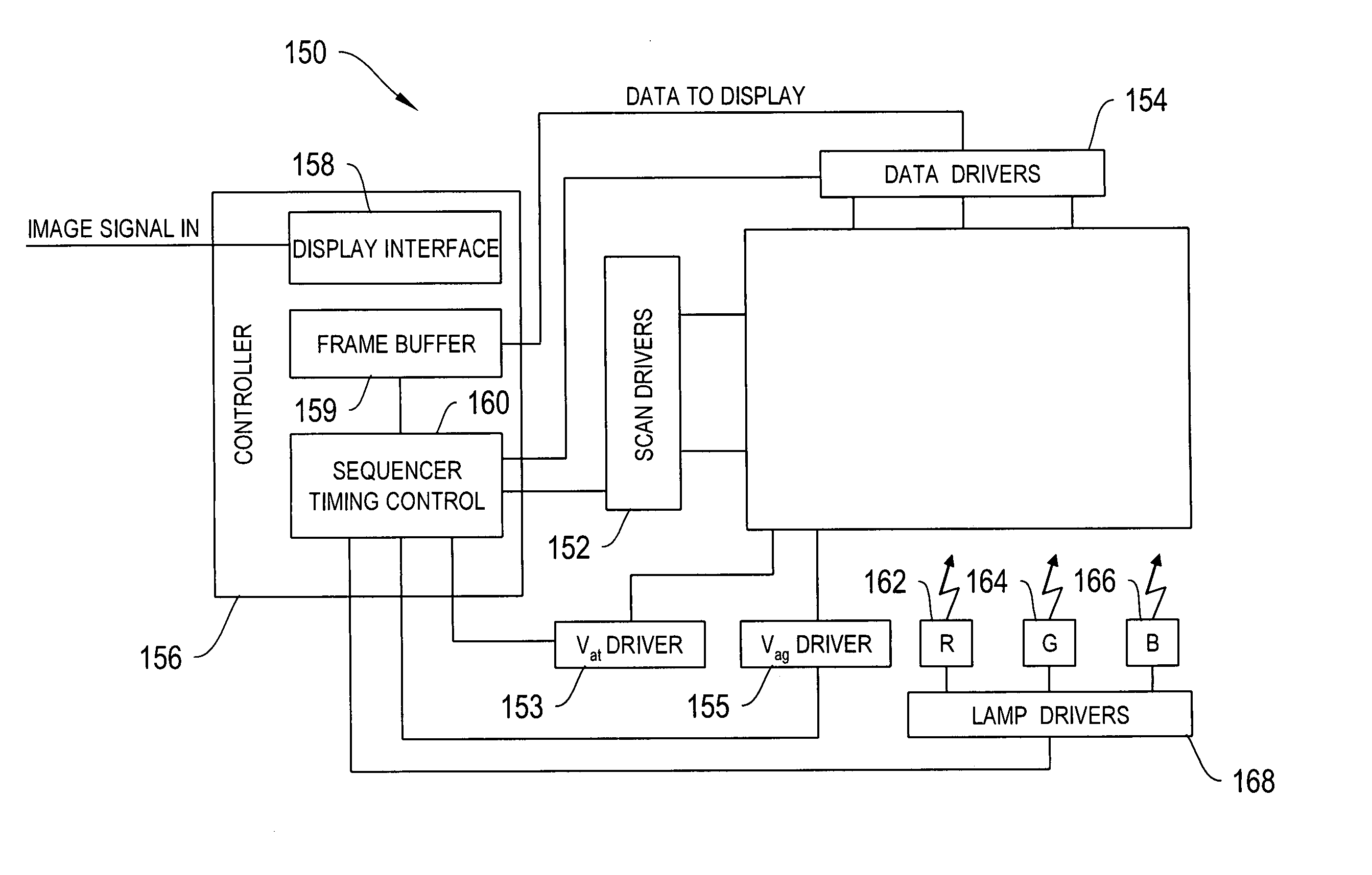
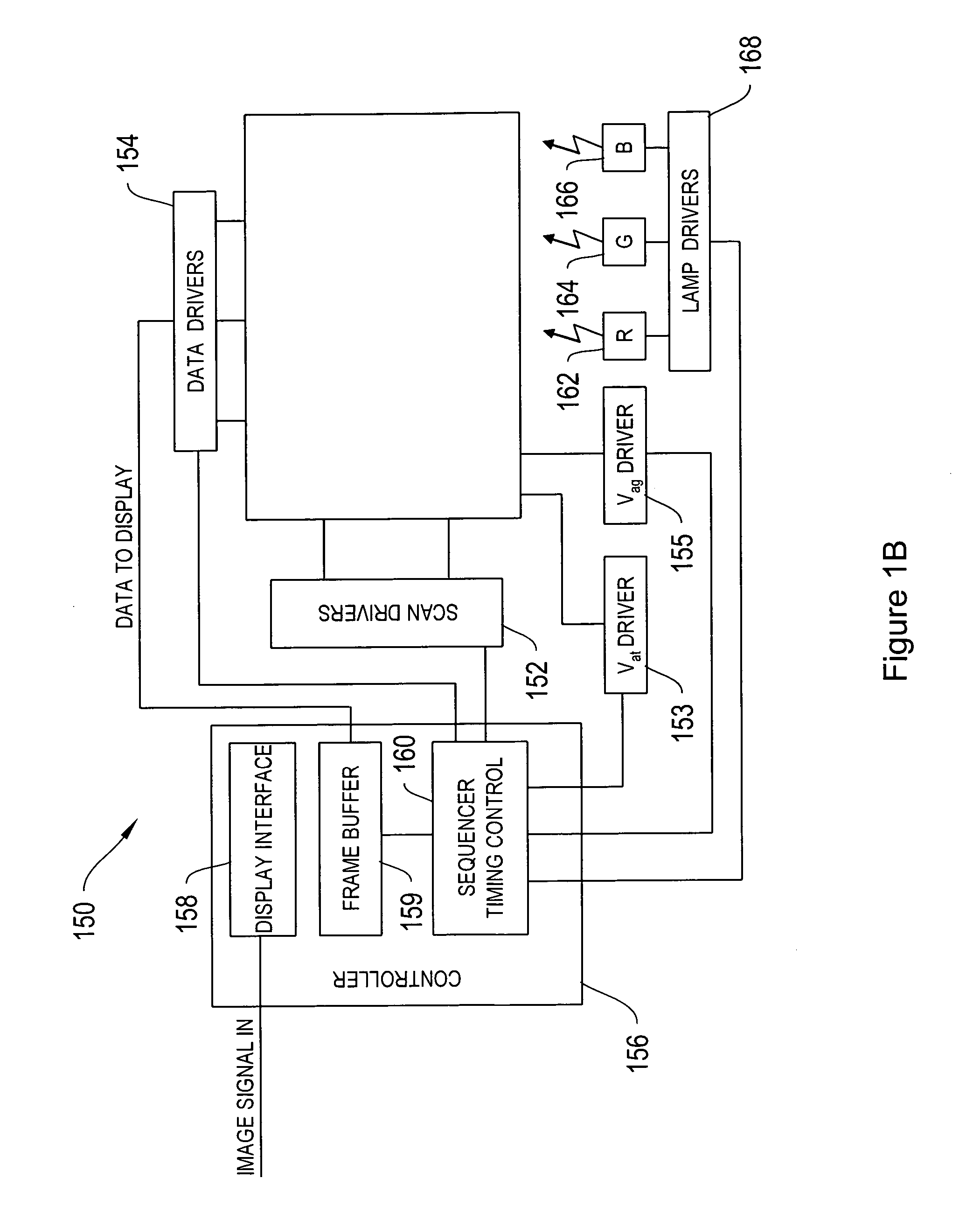
[0033] To provide an overall understanding of the invention, certain illustrative embodiments will now be described, including apparatus and methods for displaying images. However, it will be understood by one of ordinary skill in the art that the systems and methods described herein may be adapted and modified as is appropriate for the application being addressed and that the systems and methods described herein may be employed in other suitable applications, and that such other additions and modifications will not depart from the scope hereof.

[0034] This application is related to, and incorporates herein by reference, U.S. patent application Ser. No. 11 / 218,690, filed Sep. 2, 2005, U.S. patent application Ser. No. 11 / 251,035, filed Oct. 14, 2005, U.S. patent application Ser. No. 11 / 251,452, filed Oct. 14, 2005, and U.S. patent application Ser. No. 11 / 251,034, filed Oct. 14, 2005, the disclosures of which are herein incorporated by reference.

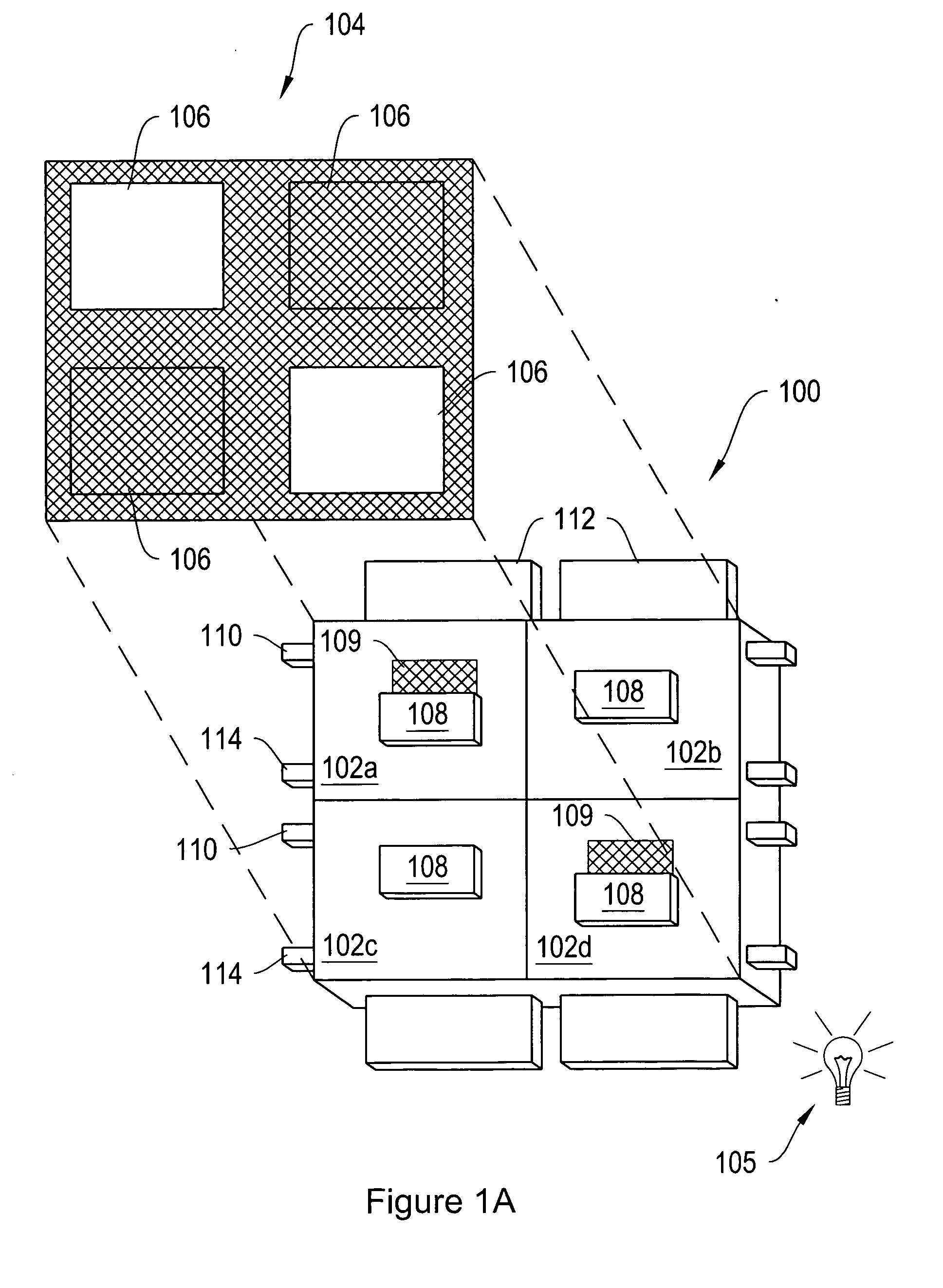
[0035]FIG. 1A is an isometric view of ...


PUM


Abstract

The invention relates to methods and apparatus for forming images on a display utilizing a control matrix to control the movement of MEMs-based light modulators.

Description

CROSS-REFERENCE TO RELATED APPLICATIONS [0001] The instant application claims priority from provisional application No. 60 / 655,827, filed Feb. 23, 2005 and provisional application No. 60 / 676,053, filed Apr. 29, 2005, the disclosures of which are incorporated herein by reference in their entirety.FIELD OF THE INVENTION [0002] In general, the invention relates to the field of imaging displays, in particular, the invention relates to circuits for controlling light modulators incorporated into imaging displays. BACKGROUND OF THE INVENTION [0003] Displays built from mechanical light modulators are an attractive alternative to displays based on liquid crystal technology. Mechanical light modulators are fast enough to display video content with good viewing angles and with a wide range of color and grey scale. Mechanical light modulators have been successful in projection display applications. Backlit displays using mechanical light modulators have not yet demonstrated sufficiently attract...

Claims


Application Information

Patent Timeline
Patent Type & Authority Applications(United States)
IPC IPC(8): G09G3/20
CPCG02B26/02G09G3/3406G09G3/3433G09G2300/08H04N5/7416G09G2310/0235G09G2310/0251G09G2310/0262G09G2310/063G09G2300/0885
Inventor HAGOOD, NESBITT W.MCALLISTER, ABRAHAMLEWIS, STEPHENBARTON, ROGER
Owner SNAPTRACK
Why Eureka
Try Eureka