Separate oil gallery for piston cooling with electronic oil flow control

Inactive Publication Date: 2005-06-09
DETROIT DIESEL CORP
View PDF10 Cites 58 Cited by
  • Summary
  • Abstract
  • Description
  • Claims
  • Application Information

AI Technical Summary

Benefits of technology

[0009] At part or low loads, the oil temperature is lower, viscosity slightly higher, and parasitic losses in the lubrication system higher than at full load. The control may be used to reduce, or interrupt, the oil flow through piston-cooling nozzles in accordance to piston cooling requirements, so that the total amount of oil being pumped through oil filter and oil cooler can be reduced, together with the pump power which is not needed. The reduction in the oil flow through the system is important because the flow through piston-cooling nozzles may comprise up to 35-40% of the total oil flow in the system, and important savings in parasitic losses and, ultimately, fuel consumption may be achieved.
[0010] In the preferred embodiment, engine thermal load, as suggested by fluid or metal temperature, or by engine torque or load, may be the determining factor, rather than engine speed. The invention also leads to improvements in the design and operation of oil coolers controlled by thermatic valves (also known as “oil thermostats”). Current designs that use an oil thermostat attempt to regulate the oil cooling in the oil cooler by varying the amount of oil flow being passed and cooled through the cooler as a function of oil temperature. In general, a desired oil temperature is a temperature that should be controlled to fall in between a minimum and maximum value. If the oil is overheated, its decrease in viscosity jeopardizes proper bearing lubrication and may lead to catastrophic engine failure in short time. There are also long term effects through increased oxidation rates at high temperatures, and oil properties deteriorations are mitigated throug

Problems solved by technology

If the oil is overheated, its decrease in viscosity jeopardizes proper bearing lubrication and may lead to catastrophic engine failure in short time.
There are also long term effects through increased oxidation rates at high temperatures, and oil properties deteriorations are mitigated through re

Method used


Image

  • Separate oil gallery for piston cooling with electronic oil flow control
  • Separate oil gallery for piston cooling with electronic oil flow control
  • Separate oil gallery for piston cooling with electronic oil flow control

Examples


Embodiment Construction

)

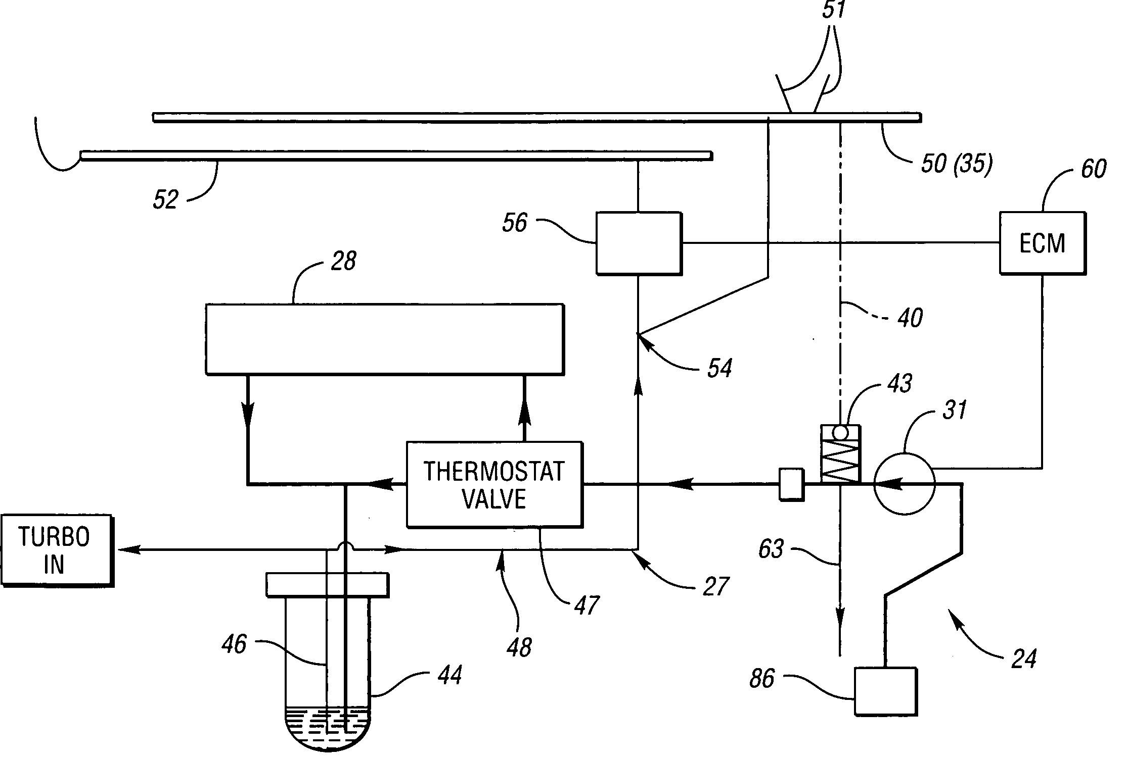
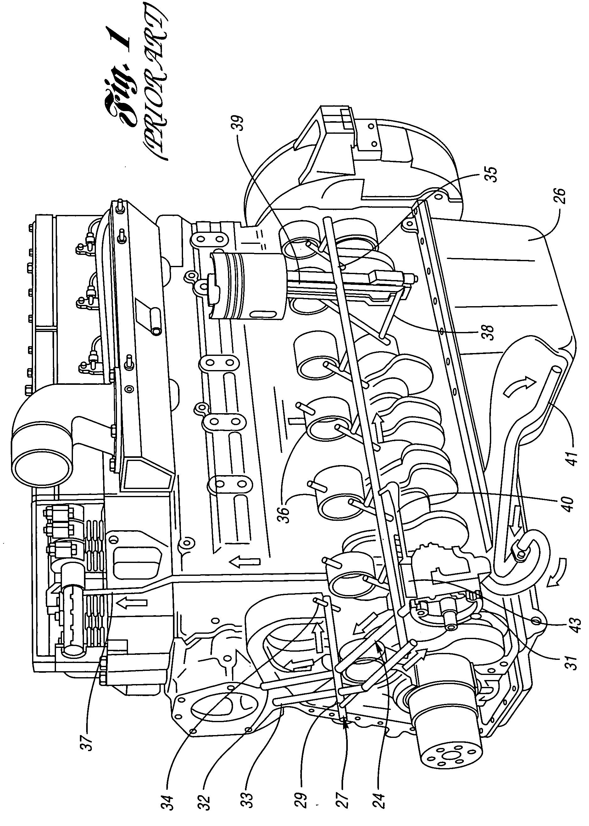
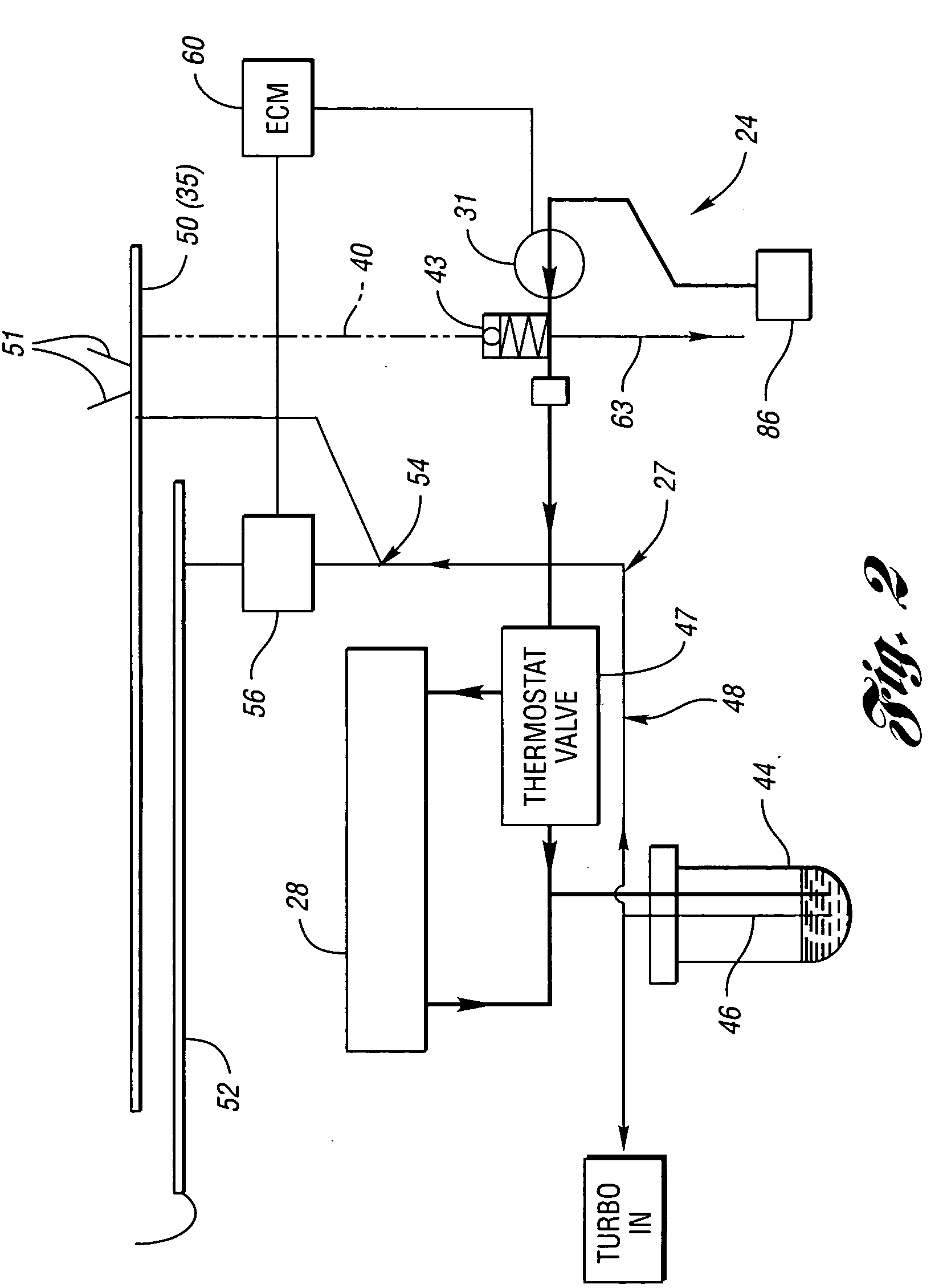
[0015] Referring first to FIG. 1, an internal combustion engine 10 is shown in a piece of equipment such as a vehicle or machinery diagrammatically represented by reference character 12. In a well known manner, the engine includes a plurality of pistons 16 (one shown) displaced in a cylinder 18 by connecting pin 20 engaged on a crank rod lobe 22. As the piston 16 compresses air and fuel injected into the cylinder 18, the heated and pressurized fuel vapor ignites and drives the piston to a retracted position within the cylinder. Since the combustion can transfer extreme heat energy to the piston and cylinder walls, the oil system often used for lubrication includes a manifold 29 that directs some of the lubricating oil to flow to the surface of the piston for cooling purposes. Oftentimes, such system provides additional heat transfer capability by passing the oil flow through a cooler coupled with the engine's coolant system. As a result, the cooled oil can absorb greater heat energ...


PUM


Abstract

An engine oil distribution system for an internal combustion engine includes a main gallery and a separate oil gallery for piston cooling nozzles. The separate gallery may be controlled by a control valve that regulates the oil flow. The oil flow to the separate gallery may be controlled by an electronic control module in accordance with the piston cooling needs, for example, varied as a function of the load applied to the engine, or as a function of engine temperature. Preferably, engine temperature is sensed by coolant fluid temperature, or directly measured metal temperature, correlated to the thermal state of the piston.

Description

BACKGROUND OF THE INVENTION [0001] 1. Field of the Invention [0002] This invention relates to oil distribution systems in compression ignition internal combustion engines, the system having a main gallery, a separate oil gallery for piston cooling nozzles and one or multiple control valves which regulate the oil flow through the separate gallery to the piston cooling nozzles, whereby the system may match the amount of oil distributed with the piston cooling demand. [0003] 2. Background Art [0004] In general, diesel engines with pistons made of steel or aluminum require piston-cooling jets as a means of removing heat from the piston during engine operation. However, piston-cooling requirements are not uniform across the engine operating range. Maximum demand for cooling occurs at full loads, at engine speeds ranging from peak torque to rated speed, when engine thermal loading is high. If the emissions control strategy includes running the engine at retarded beginning of injection (BO...

Claims


Application Information

Patent Timeline
IPC IPC(8): F01M1/08F01M1/10F01P3/00F01P3/08F01P7/14F01P7/16
CPCF01M1/08F01M1/10F01M2005/004F01P2060/04F01P7/16F01P2003/006F01P2007/146F01P3/08
Inventor DUCU, DAN OCTAVIAN
Owner DETROIT DIESEL CORP
Why Eureka
Try Eureka