Hydraulic control impact load launching valve

A technology of impact load and hydraulic control, which is applied in the direction of fluid pressure actuators, servo meter circuits, servo motor components, etc., can solve the problems of difficulty in meeting medium and high-speed launch requirements, uncontrollable launch process, long launch acceleration distance, etc., to achieve Reduce the cost of preparation, not easy to get stuck in motion, and improve the effect of lubrication

Pending Publication Date: 2021-11-12
NAVAL UNIV OF ENG PLA
View PDF0 Cites 0 Cited by
  • Summary
  • Abstract
  • Description
  • Claims
  • Application Information

AI Technical Summary

Problems solved by technology

However, this kind of pneumatic hydraulic launching device generally has the following disadvantages: ①The impact overload is large, and the launching process is uncontrollable; ②The launching acceleration distance is long and the deceleration is slow; ③It is difficult to meet the needs of medium and high-speed launching

Method used


Image

  • Hydraulic control impact load launching valve
  • Hydraulic control impact load launching valve
  • Hydraulic control impact load launching valve

Examples


Embodiment Construction

[0025] The present invention will be further described in detail below in conjunction with the accompanying drawings and specific embodiments to facilitate a clear understanding of the present invention, but they do not limit the present invention.

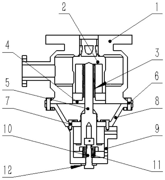
[0026] Such as figure 1 As shown, the present invention provides a hydraulically controlled shock load launch valve, which includes two parts, a launch main valve and a buffer. Oil circuit or air circuit; the lower part of the launch valve is a buffer, which is used to control the speed and size of the launch power output.

[0027] Wherein: the launch main valve includes a main valve body 1, a main valve core 2, a first spring 3 and a main valve cover 4, etc.; the buffer includes a primary buffer piston 5, bolts 6, 7, a connecting flange 8, Buffer cylinder 9, secondary buffer piston 10, second spring 11, adjusting gasket 12, etc. The connecting flange 8 not only serves as the cylinder head of the buffer cylinder to realize the s...


PUM


Abstract

The invention provides a hydraulic control impact load launching valve. The valve comprises a main valve body; a launching power output port is formed in the top of the main valve body, and communicates with the outside; a pressure chamber is arranged in the main valve body and communicates with the launching power output port; the pressure chamber is used for being connected with external hydraulic oil or hydraulic gas to serve as launching power; a main valve core is further arranged in the main valve body; the top of the main valve core is clamped in and sleeved with the launching power output port; the middle of the main valve core is matched with the pressure chamber to form a closed annular cavity; the bottom of the main valve core is clamped in and sleeved with the bottom of the main valve body, and the contact surfaces of the main valve core and the main valve body are tightly attached; a main valve cover is arranged on the bottom face of the main valve body; and the main valve cover, the inner wall of a first blind hole of the main valve core and the inner wall of the bottom of the main valve body form a closed structure. The hydraulic control impact load launching valve is suitable for outputting hydraulic or pneumatic power according to a preset curve to launch medium-high-speed impact loads, so that the loads move according to a set rule.

Description

technical field [0001] The invention belongs to the technical field of hydraulic control, and in particular relates to a hydraulically controlled shock load launching valve. Background technique [0002] Shock load launching devices powered by hydraulic pressure or pneumatic pressure usually need to respond to launch commands in a short time, and output hydraulic or pneumatic power according to a preset regular curve, while the output of pneumatic hydraulic power can be realized by the launch valve. [0003] A typical pneumatic-hydraulic launching device is mainly composed of a pneumatic or hydraulic power source, an electromagnetic reversing valve, a variable flow valve and its accessories. However, this type of pneumatic-hydraulic launching device generally has the following disadvantages: ① large shock overload, uncontrollable launching process; ② long acceleration distance and slow deceleration; ③ difficult to meet the needs of medium and high-speed launching. Contents...

Claims


Application Information

Patent Timeline
Patent Type & Authority Applications(China)
IPC IPC(8): F15B13/04F15B13/042
CPCF15B13/0405F15B13/0407F15B2211/528
Inventor 邓璐李想欧阳斌马名中张成亮马锐锋郭威李德南
Owner NAVAL UNIV OF ENG PLA
Why Eureka
Try Eureka