Sintered bearing

A technology of sintered bearings and sintered metals, applied in bearings, liquid cushion bearings, bearing components, etc., can solve problems such as narrow degrees of freedom, and achieve the effects of expanding degrees of freedom, high wear resistance, and reducing oil penetration

Active Publication Date: 2015-10-21
NTN CORP
View PDF10 Cites 0 Cited by
  • Summary
  • Abstract
  • Description
  • Claims
  • Application Information

AI Technical Summary

Problems solved by technology

Therefore, conditions such as the ratio of copper to iron, sintering density, or sintering temperature are clearly limited, and the degree of freedom in design becomes very narrow.

Method used


Image

  • Sintered bearing
  • Sintered bearing
  • Sintered bearing

Examples


Embodiment Construction

[0039] Hereinafter, embodiments of the present invention will be described based on the drawings.

[0040] Figure 6 The spindle motor shown is used in a disk drive device such as an HDD, and includes: a fluid dynamic pressure bearing device 1 that supports a shaft member 2 in a non-contact manner so as to be rotatable; a hub 3 mounted on the shaft member 2; and a stator opposed to each other through a gap. Coil 4 and rotor magnet 5. The stator coil 4 is mounted on the outer periphery of the motor bracket 6 , and the rotor magnet 5 is mounted on the inner periphery of the hub 3 . Disc hub 3 maintains one or more sheets (in Figure 6 Two in the middle) Disk D. In the spindle motor configured in this way, when the stator coil 4 is energized, the rotor magnet 5 rotates, and accordingly, the disk hub 3 and the disk D held by the disk hub 3 rotate integrally with the shaft member 2 .

[0041] Such as Figure 7 As shown, the main structural elements of the fluid dynamic pressur...


PUM

PropertyMeasurementUnit
diameteraaaaaaaaaa
densityaaaaaaaaaa
diameteraaaaaaaaaa

Abstract

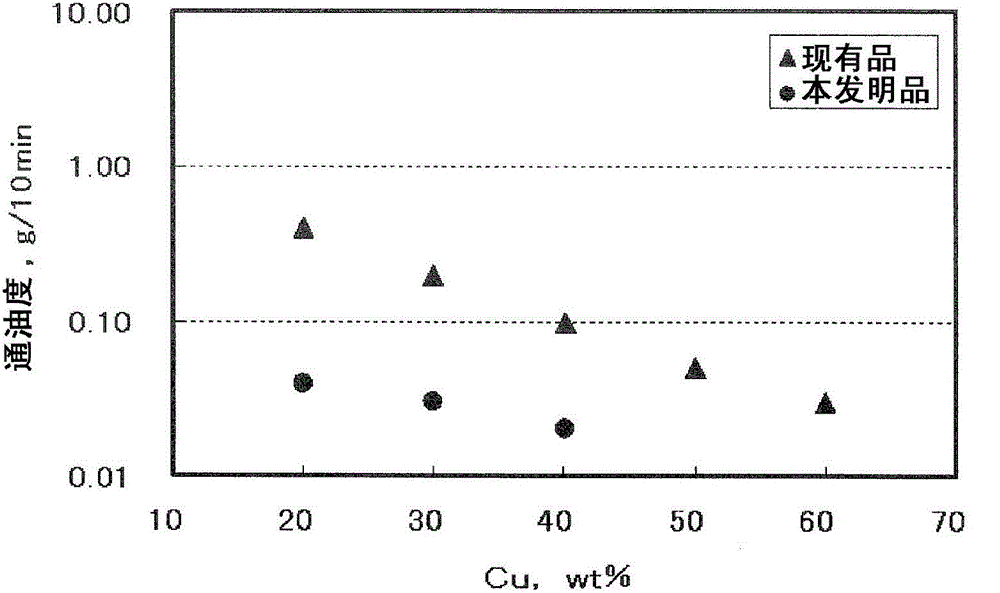
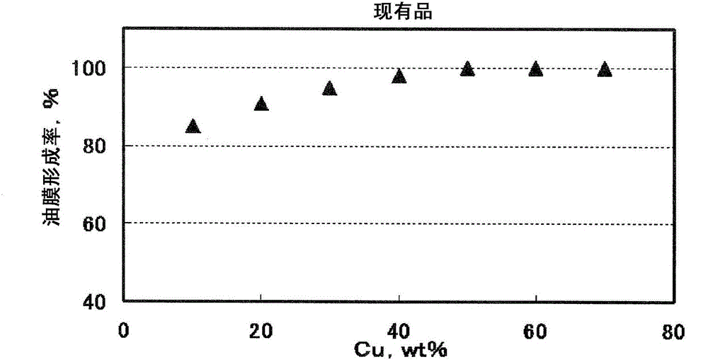
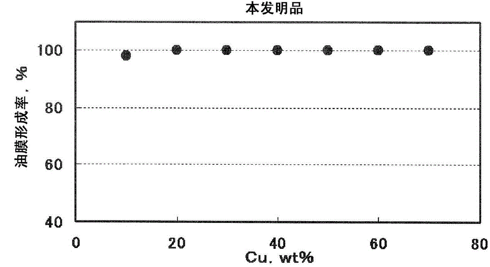
With use of a fine copper-based powder, specifically a copper-based powder that contains particles each having a diameter of 45 mum or less by 80 weight % or more, an air permeability can be significantly reduced. When this copper-based powder is used, a sintered metal can be easily formed to contain copper by 40% or less (contain iron by 60% or more) to enhance abrasion resistance, and to have an oil permeability of 1.00 g / 10 min or less to increase an oil film formation rate.

Description

technical field [0001] The invention relates to a sintered bearing, in particular to a copper-iron sintered bearing. Background technique [0002] Sintered bearings are used by impregnating lubricating oil in the internal pores. As the sintered bearing and the shaft rotate relative to each other, the lubricating oil impregnated inside the sintered bearing oozes out to the sliding portion between the sintered bearing and the shaft to form an oil film, and the shaft is supported through the oil film. Such a sintered bearing is preferably used as a fluid dynamic pressure bearing incorporated in a motor spindle for information equipment due to its high rotational accuracy and quietness (for example, refer to Patent Document 1). [0003] prior art literature [0004] patent documents [0005] Patent Document 1: Japanese Patent Laid-Open No. 2001-279349 [0006] Summary of the invention [0007] The problem to be solved by the invention [0008] In sintered bearings, there a...

Claims


Application Information

Patent Timeline
Patent Type & Authority Patents(China)
IPC IPC(8): F16C33/10F16C17/10F16C33/12F16C33/14B22F1/052
CPCF16C32/0629B22F1/0014B22F3/12C22C38/16F16C17/107F16C33/104F16C2204/10F16C2240/48F16C33/121F16C33/128F16C2370/12B22F1/052
Inventor 伊藤冬木森夏比古
Owner NTN CORP
Why Eureka
Try Eureka