Fiber optically coupled, multiplexed, and chopped laser rangefinder

Inactive Publication Date: 2009-02-19
NATIONAL UNITED UNIVERSITY
View PDF15 Cites 59 Cited by
  • Summary
  • Abstract
  • Description
  • Claims
  • Application Information

AI Technical Summary

Benefits of technology

[0028]Another embodiment of the present invention is a laser rangefinder with a

Problems solved by technology

Limitations in the prior art, e.g., Payne, et al., do not permit the requisite length measurement accuracy.
Limitations include variable phase delays in the detector due to beam spot position uncertainty, run-out of the steering mirror leading to systematic range errors, low rates of zero-point measurements (and equivalently, low chopping rates) leadi

Method used


Image

  • Fiber optically coupled, multiplexed, and chopped laser rangefinder
  • Fiber optically coupled, multiplexed, and chopped laser rangefinder
  • Fiber optically coupled, multiplexed, and chopped laser rangefinder

Examples


examples

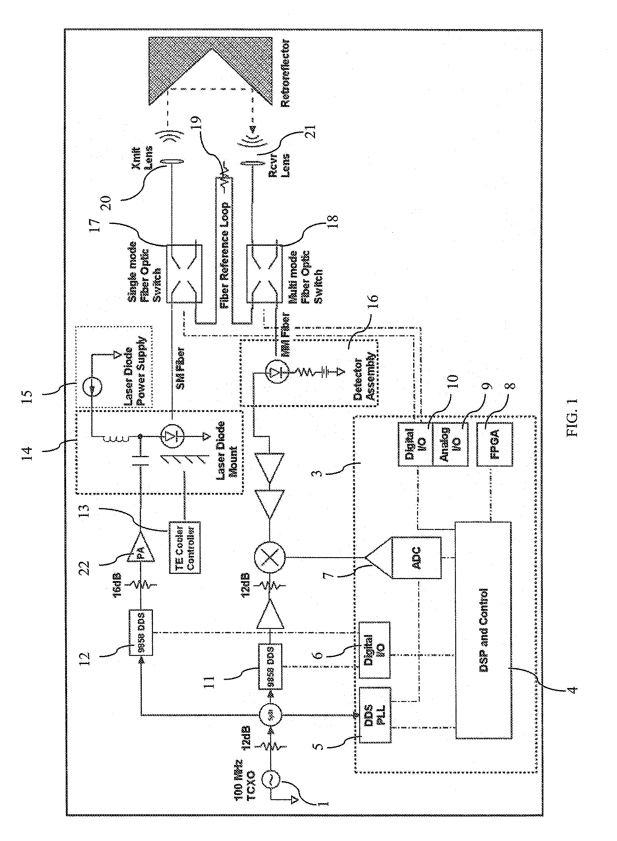
[0055]In operations of the present invention, differential range between transmitter / receiver optics and a hollow retroreflector mounted on the three-axis translation stage were measured at approximately a 1 Hz rate. The nominal distance between them was 20 meters. The transmit beam and the receive beams were collimated with effective IFOV (Instantaneous Field of View) to the half-power diameter of approximately 1.0 and 2.5 milliradians, respectively. Path group index was calculated every two minutes using eight air temperature sensors, barometric pressure, and relative humidity. The local oscillator frequency for all experiments was 203.125 MHz, with transmit frequencies offset by integral multiples of 1525.87890625 Hz. In most cases 8192 samples of all four signal paths were taken, and at powers of two divisors of 48828.125 Hz.

[0056]FIG. 3 illustrates the results of a long term (10 day) range stability test. The first two panels, showing the estimated distance-equivalent phase, cl...


PUM


Abstract

A CW phase-delay distance measuring device is described. The device fiber-optically couples an amplitude modulated laser and a detector though MEMS fiber optic switches to provide chopping and multiplexing capability, and to allow measurement of transmit and receive coupling. Phase continuous direct digital synthesizers are used to generate transmit and local oscillator frequencies in an agile frequency diverse way to disambiguate range. Fiber-optic coupling mitigates systematic errors such as variable detector group delay and provides for multiplexing multiple transmit and receive optics onto a single electro-optical system.

Description

CLAIM OF PRIORITY[0001]This application claims priority to U.S. Provisional Application No. 60 / 881,172 entitled “Fiber Optically Coupled, Multiplexed, and Chopped High Precision Laser Rangefinder” filed Jan. 19, 2007, the entirety of which is specifically incorporated by reference.RIGHTS IN THE INVENTION[0002]This invention was made with government support under Cooperative Agreement AST-0223851, between the National Science Foundation and Associated Universities, Inc., and, accordingly, the United States government has certain rights in this invention.BACKGROUND[0003]1. Field of the Invention[0004]This invention is directed to electro-optical distance measuring apparatus and methods, and, in particular, amplitude modulated and heterodyne detected continuous wave (CW) laser phase delay distance measuring equipment.[0005]2. Background of the Invention[0006]Large-scale metrology includes the measurement of coordinates over large distances, for example, greater than the volume of a con...

Claims


Application Information

Patent Timeline
IPC IPC(8): G01C3/08
CPCG01S7/4811G01S17/36G01S7/497
Inventor CONSTANTIKES, KIM THEODORE
Owner NATIONAL UNITED UNIVERSITY
Why Eureka
Try Eureka