Analyte sensor method of making the same

a technology of analyte sensor and sensor body, which is applied in the field of analyte sensor, can solve the problems of time-consuming and expensive step procedures

Inactive Publication Date: 2006-02-21
MEDTRONIC MIMIMED INC
View PDF27 Cites 1178 Cited by
  • Summary
  • Abstract
  • Description
  • Claims
  • Application Information

AI Technical Summary

Benefits of technology

[0008]According to an embodiment of the invention, a sensor and a method of making the same for implantation in a body includes a substrate with notches cut in the substrate to form a necked down region in the substrate; and at least one sensor electrode formed from one or more conductive layers. In preferred embodiments, the thickness of the substrate ranges from approximately 25μ to 350μ, but the thickness of the substrate can range from 5μ to 750μ. In particular embodiments, a sensor assembly includes the sensor and a slotted needle having a slot. The notches creating the necked down region allow the substrate to slide into the slotted needle, which that has the slot narrow enough to permit passage of the necked down region. However, a non-necked down region of the substrate is prevented from pulling out of the slotted needle through the slot. In other embodiments, the slot of the slotted needle permits the necked down region of the substrate to slide down the slot.
[0029]In accordance with further embodiments of the present invention, sensors produced according to the foregoing methods are also provided. In accordance with other embodiments of the present invention, sensor sets that include sensors, as described herein, together with appropriate mounting bases and insertion needles are provided. In additional embodiments, the sensor sets include cannula in which portions of the sensor are disposed and which in turn are at least partially disposed within the insertion needles. In other embodiments, the sensor includes a bead, which is at least partially nested within the insertion needle, obviating the need for a cannula.

Problems solved by technology

Etching processes are often multi-step procedures that can be time-consuming and expensive.

Method used


Image

  • Analyte sensor method of making the same
  • Analyte sensor method of making the same
  • Analyte sensor method of making the same

Examples


first embodiment

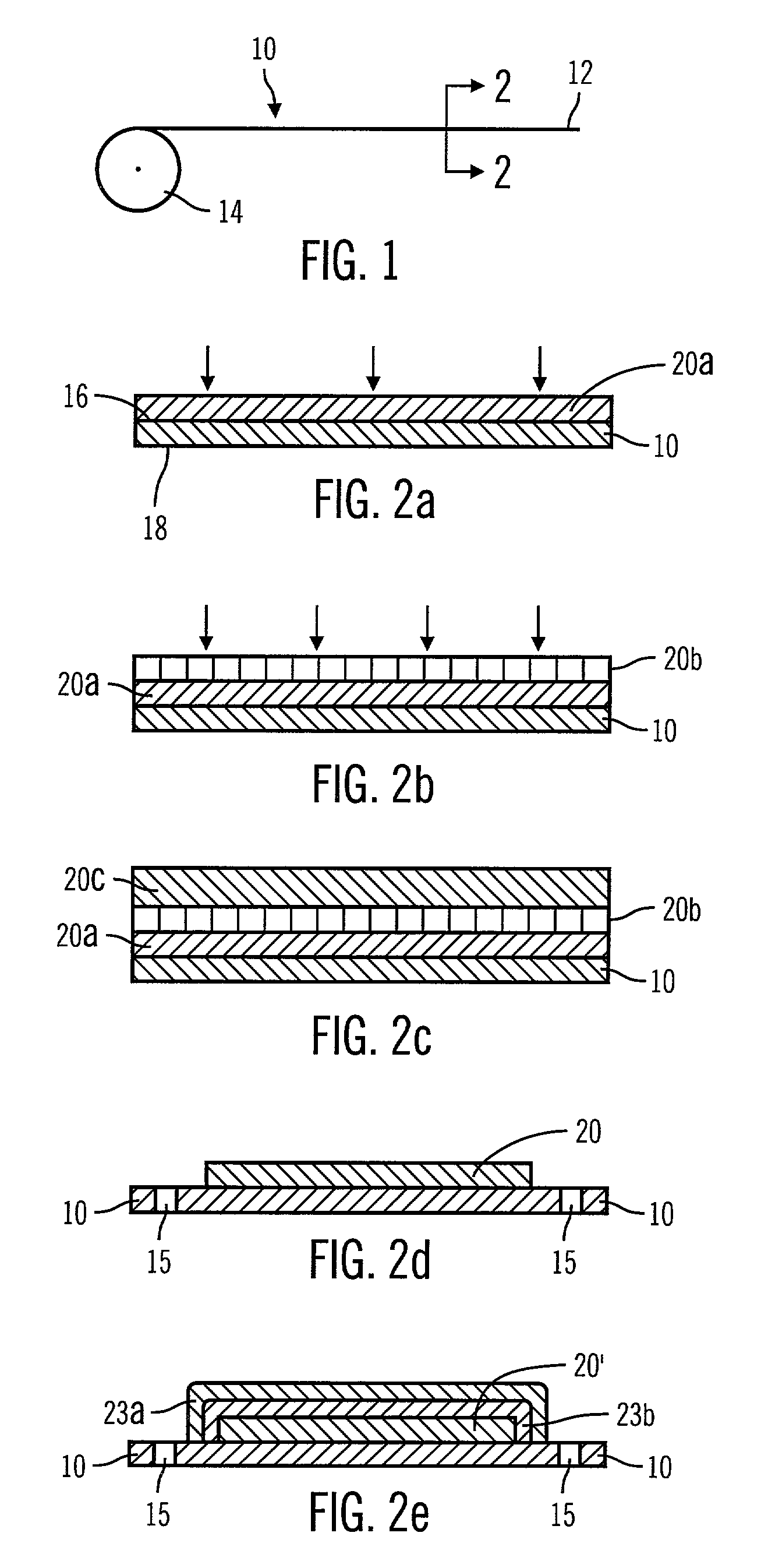
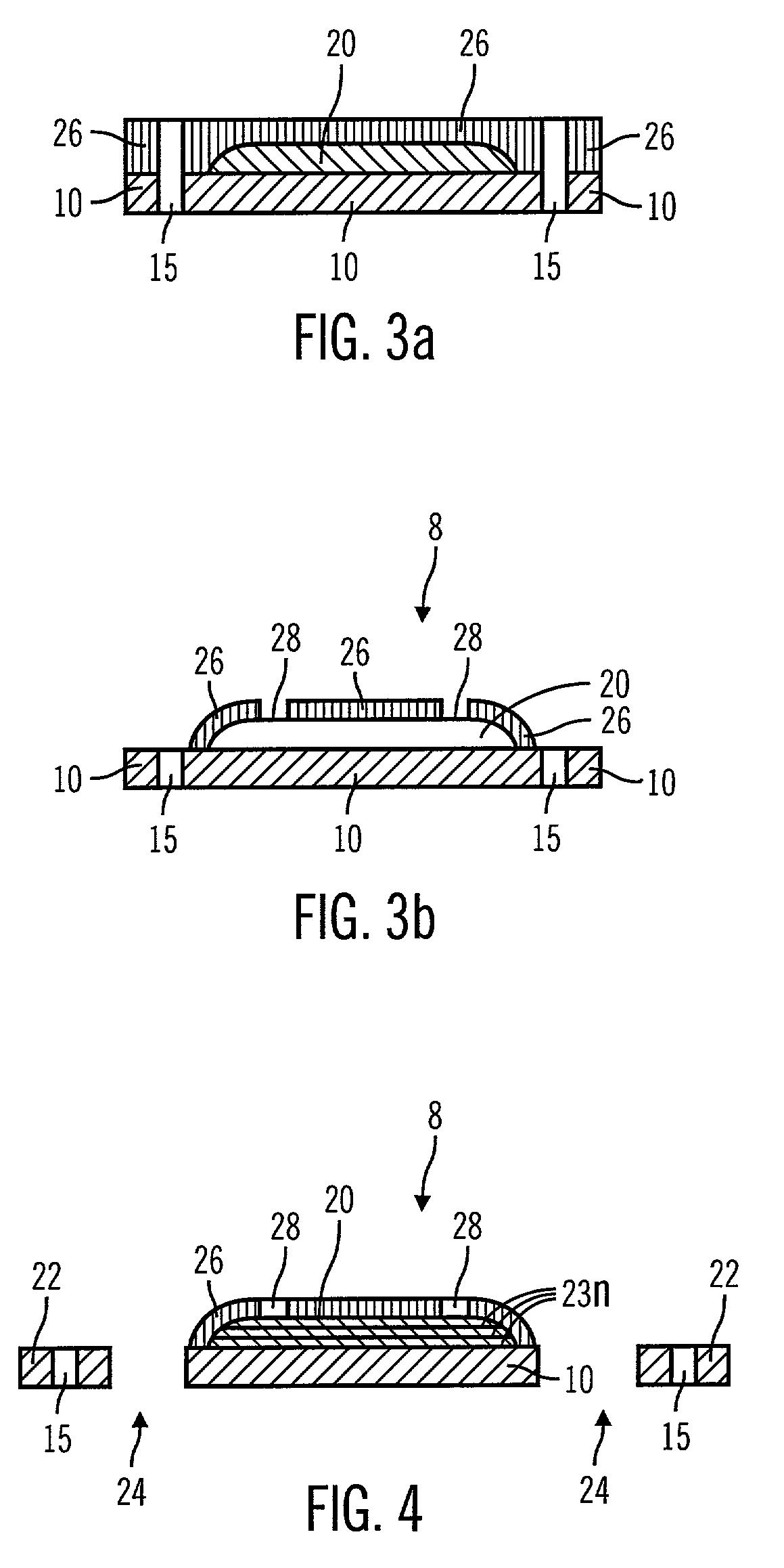
[0073]Referring now to FIGS. 1–4, a substrate 10 is provided in accordance with the inventive method. In preferred embodiments, substrate 10 is a flexible, self-supporting substrate in the form of a continuous tape 12 supplied from a reel 14. The continuous tape 12 is preferably formed from a polymeric material such as a polyimide. However, other flexible, self-supporting materials can be used. The thickness of tape 12 is preferably about 10μ to 125μ. However, in alternative embodiments, thinner or thicker films from 5μ to 500μ may be used. In particular embodiments, sprocket holes 15 (see FIG. 2c) are formed in the substrate adjacent the outer edge of the tape 12 to facilitate manufacturing of the sensors through automated processes. For instance, the tape 12 is fed through stages that perform various steps of the methods described in this application. Sensor electrodes 20 can be formed on the tape 12 using techniques described in “3M Specifications and Design Guidelines, Microflex...

second embodiment

[0108] a non-impact process is used to form the sensor electrodes 324. Exemplary non-impact processes include electrophotography and magnetography, in which an image of the conductive traces is electrically or magnetically formed on a drum 320. The image attracts a toner material 322 to the drum. The toner 322 material is subsequently transferred to the substrate 310, for example by rolling, followed preferably by a curing step to adhere the toner material to the substrate. See FIG. 24. Other useful non-impact processes include ink jet printing and piezo jet printing, in which an image is formed by ejection of a conductive material, such as a conductive ink, onto the substrate. Still other useful non-impact processes include the use of photosensitive resins to form a layer on the substrate in which channels are defined, followed by filling the channels with conductive material to form the sensor electrodes.

third embodiment

[0109] a film of conductive material 332 is formed, for example, as a continuous sheet or as a coating layer deposited on a carrier film 330. The film is brought, for example, between a print head 334 and the substrate 310. A pattern of sensor electrodes 336 is formed on the substrate 310 using the print head. The conductive material is transferred by pressure and / or heat to the substrate 310. See FIGS. 25a–b. Channels can be formed in the substrate as a result of the printing process, or alternatively the conductive material can be deposited on the substrate substantially without the formation of depressions or channels.

[0110]Once the sensor electrodes have been formed, a bead 342 can be provided in accordance with the methods described above.

[0111]FIGS. 26–29 illustrate a sensor 400 formed in accordance with another embodiment of the present invention. The sensor 400 includes a substrate 402 and at least one sensor electrode 404 formed from one or more conductive layers. In partic...


PUM


Abstract

A sensor and method of making the same for implantation in a body that includes a substrate with notches cut in the substrate to form a necked down region in the substrate; and at least one sensor electrode formed from one or more conductive layers. Preferably, the thickness of the substrate ranges from approximately 25μ to 350μ, but the thickness of the substrate can range from 5μ to 750μ. The sensor may be incorporated in to a sensor assembly includes a slotted needle having a slot. The notches creating the necked down region allow the substrate to slide into the slotted needle, which that has the slot narrow enough to permit passage of the necked down region. However, a non-necked down region of the substrate is prevented from pulling out of the slotted needle through the slot. The slot of the slotted needle may also permit the necked down region of the substrate to slide down the slot.

Description

RELATED APPLICATIONS[0001]This application is a continuation of U.S. patent application Ser. No. 09 / 502,444, filed Feb. 11, 2000, now abandoned which is a continuation of U.S. patent application Ser. No. 09 / 502,204 filed Feb. 10, 2000 now U.S. Pat. No. 6,484,045, both of which are specifically incorporated by reference.FIELD OF THE INVENTION[0002]The present invention relates to methods for producing sensors that include flexible substrates and one or more sensor electrodes, and in particular embodiments to sensor sets including such sensors.BACKGROUND OF THE INVENTION[0003]Methods for producing sensors, particularly sensors useful in sensor sets for the determination of a body characteristic such as blood glucose levels, are known. Examples of such sensors, sensor sets and methods for production thereof are described, e.g., in commonly assigned U.S. Pat. No. 5,390,691; No. 5,391,250; No. 5,482,473; No. 5,299,571; No. 5,586,553; and No. 5,568,806, each of which is incorporated in it...

Claims


Application Information

Patent Timeline
Patent Type & Authority Patents(United States)
IPC IPC(8): B65D85/38A61B5/04A61B5/05A61B5/00
CPCA61B5/14865A61B5/6849A61M2005/1726
Inventor HOLKER, JAMES D.CALLE, GUILLERMO A.BRANCH, KEVIN D.MASTROTOTARO, JOHN J.VAN ANTWERP, WILLIAM P.VAN ANTWERP, NANNETTE
Owner MEDTRONIC MIMIMED INC
Why Eureka
Try Eureka