Minimally invasive valve replacement system

a valve replacement and minimally invasive technology, applied in the field of physiological valve replacement devices and systems, can solve the problems of increased hydrostatic pressure, changes in skin color, pain, swelling and edema, etc., and achieve the effects of reducing the time spent in surgery, avoiding or reducing the need for suturing, and minimizing the risks of surgery

Active Publication Date: 2005-04-07
MEDTRONIC 3F THERAPEUTICS
View PDF38 Cites 524 Cited by
  • Summary
  • Abstract
  • Description
  • Claims
  • Application Information

AI Technical Summary

Benefits of technology

[0009] The present invention provides systems and devices for the replacement of physiological valves. In one embodiment of the present invention, the replacement valve assemblies are adapted to fit substantially within the valve sinuses. Because the devices and procedures

Problems solved by technology

When valves exhibit abnormal anatomy and function as a result of valve disease or injury, the unidirectional flow of the physiological fluid they are designed to regulate is disrupted, resulting in increased hydrostatic pressure.
For example, venous valvular dysfunction leads to blood flowing back and pooling in the lower legs, resulting in pain, swelling and edema, changes in skin color, and skin ulcerations that can be extremely difficult to treat.
Lymphatic valve insufficiency can result in lymphedema with tissue fibrosis and gross distention of the affected body part.
Regardless of their etiology, all valvular diseases result in either stenosis, in which the valve does not open properly, impeding fluid flow across it and causing a rise in fluid pressure, or insufficiency/regurgitation, in which the valve does not close properly

Method used


Image

  • Minimally invasive valve replacement system
  • Minimally invasive valve replacement system
  • Minimally invasive valve replacement system

Examples


Embodiment Construction

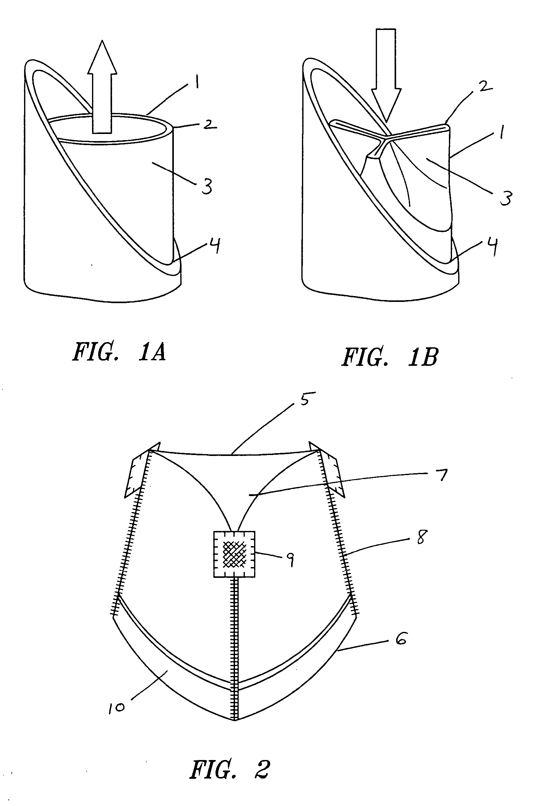
[0077] The present invention relates to valve replacement systems and devices. As illustrated in FIG. 1, a valve (1) comprises a distal or outflow end (2), leaflets (3) and a proximal or inflow end (4). A typical valve functions similar to a collapsible tube in that it opens widely during systole or in response to muscular contraction, to enable unobstructed forward flow across the valvular orifice (FIG. 1A). In contrast, at the end of systole or contraction, as illustrated in FIG. 1B, as forward flow decelerates, the walls of the tube are forced centrally between the sites of attachment to the vessel wall and the valve closes completely.

[0078] Replacement Valves

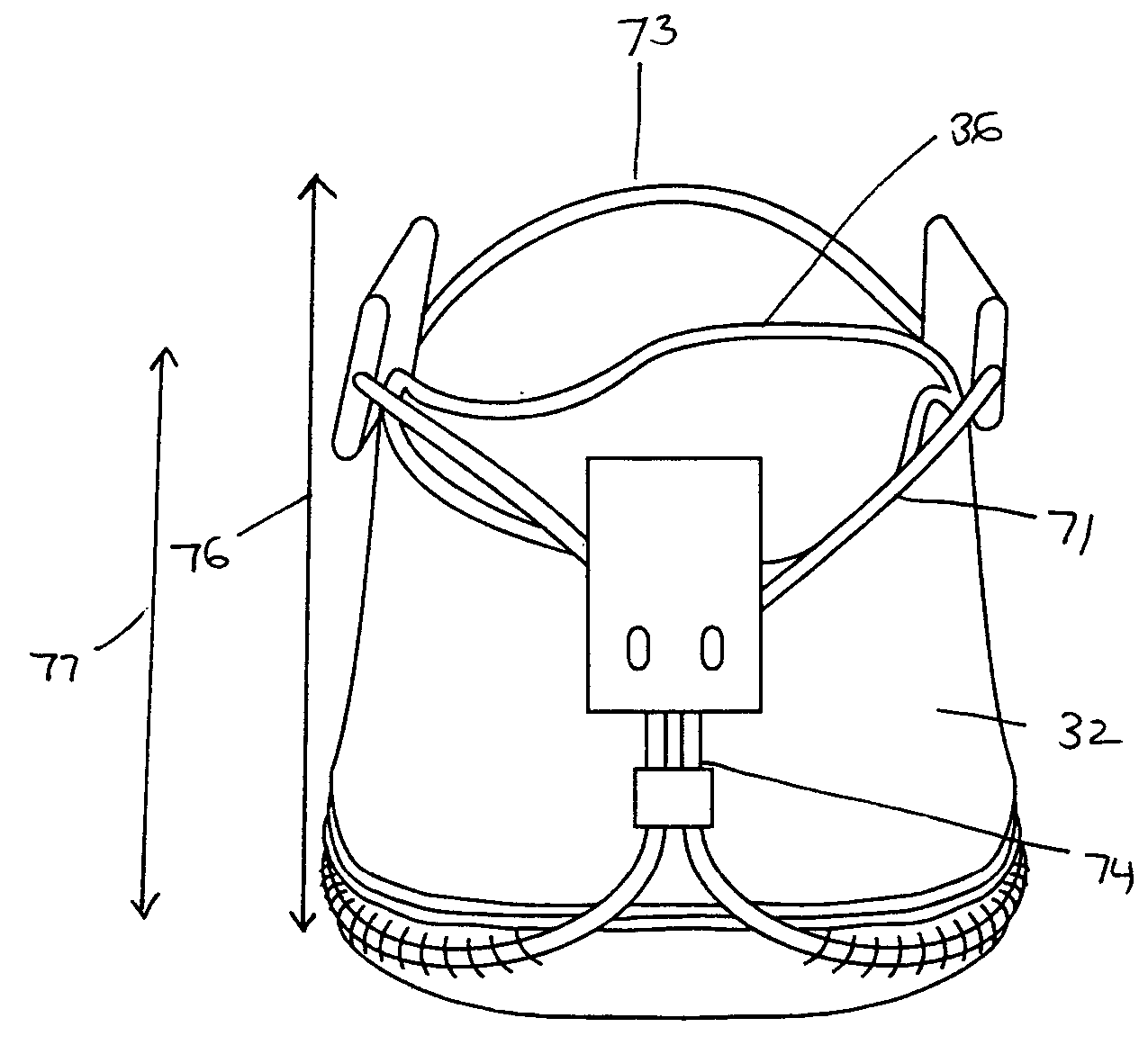
[0079] A preferred valve (5) for use with the systems and devices of the present invention is illustrated in FIG. 2 and is comprised of a body having a proximal end or inflow ring (6) and a distal end or outflow ring (7). The body is comprised of multiple leaflets of valve tissue joined by seams (8), wherein each seam is f...


PUM


Abstract

Methods and systems for minimally invasive replacement of a valve. The system includes a collapsible valve and anchoring structure, devices and methods for expanding the valve anchoring structure, adhesive means to seal the valve to the surrounding tissue, a catheter-based valve sizing and delivery system, native valve removal means, and a temporary valve and filter assembly to facilitate removal of debris material. The valve assembly comprises a valve and anchoring structure for the valve, dimensioned to fit substantially within the valve sinus.

Description

FIELD OF THE INVENTION [0001] The present invention relates to devices and systems for the replacement of physiological valves. BACKGROUND OF THE INVENTION [0002] The transport of vital fluids in the human body is largely regulated by valves. Physiological valves are designed to prevent the backflow of bodily fluids, such as blood, lymph, urine, bile, etc., thereby keeping the body's fluid dynamics unidirectional for proper homeostasis. For example, venous valves maintain the upward flow of blood, particularly from the lower extremities, back toward the heart, while lymphatic valves prevent the backflow of lymph within the lymph vessels, particularly those of the limbs. [0003] Because of their common function, valves share certain anatomical features despite variations in relative size. The cardiac valves are among the largest valves in the body with diameters that may exceed 30 mm, while valves of the smaller veins may have diameters no larger than a fraction of a millimeter. Regar...

Claims


Application Information

Patent Timeline
IPC IPC(8): A61F2/01A61F2/06A61F2/24A61F2/76A61F2/90
CPCA61F2/013A61F2/2418A61F2/243A61F2/2439A61F2/2496A61F2210/0019A61F2230/0054A61F2250/0059A61F2220/0008A61F2220/0016A61F2220/005A61F2220/0066A61F2220/0075A61F2210/0028
Inventor ARTOF, JASONNGUYEN, TUOC TANMYERS, KEITH E.
Owner MEDTRONIC 3F THERAPEUTICS
Why Eureka
Try Eureka