

Systems and Methods for Acid Gas Removal
a technology of acid gas removal and system, applied in the direction of separation processes, hydrogen sulfides, sulfur compounds, etc., can solve the problems of high gas-liquid exchange rate, process challenges, and salts are thermally unstable, so as to reduce the pressure drop through the system, reduce the cost, and reduce the capital investment
Inactive Publication Date: 2011-09-08
EXXON RES & ENG CO
View PDF9 Cites 89 Cited by
- Summary
- Abstract
- Description
- Claims
- Application Information
AI Technical Summary
Benefits of technology
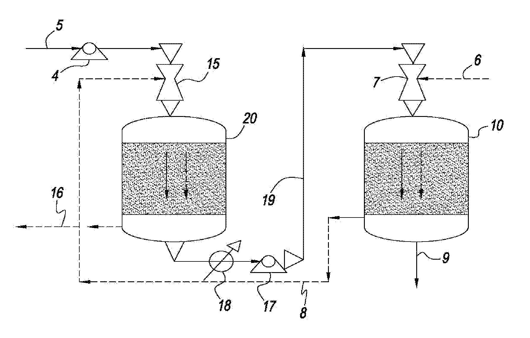
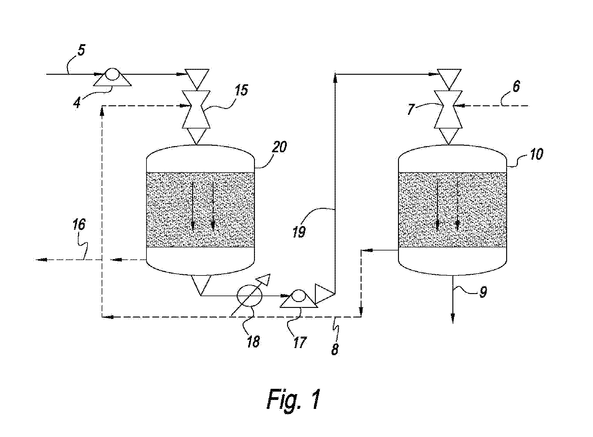
[0043]The systems and methods of this disclosure provide a low capital investment process for CO2 capture with absorbent solutions, e.g., amines or other solutions that can affect the absorption of CO2. The use of ejector venturi nozzles in the systems and methods of this disclosure eliminates the need for expensive fans / blowers for drafting a gas mixture, e.g., flue gas, into the absorbent contactors and to overcome the pressure drop in the contactors. The kinetic energy for overcoming the pressure drop comes from the high pressure liquid pumps, e.g., ejector venturi nozzles, which are significantly less expensive than fans / blowers. The co-current designs of the present invention also reduce the pressure drop through the systems. The systems and methods of this disclosure also reduce or eliminate the need for expensive demisters.
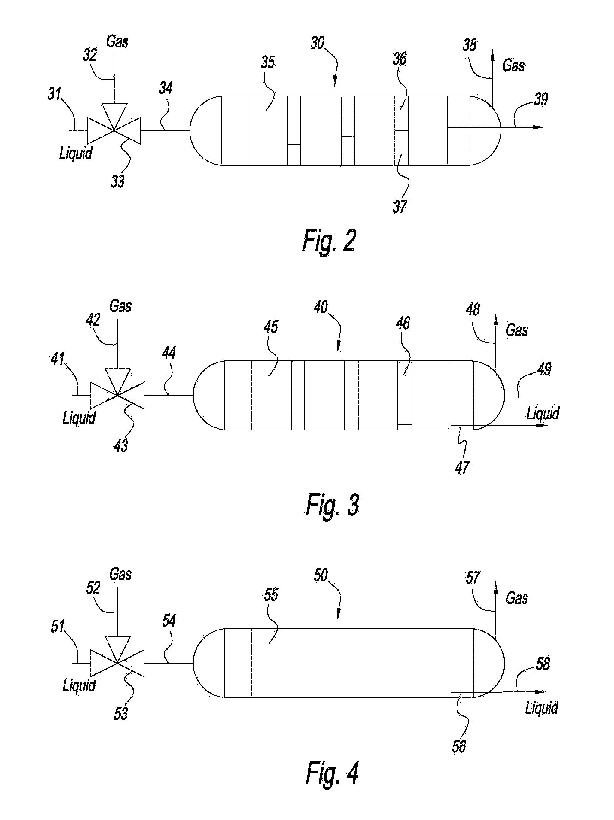
[0044]In addition, the absorbent contactors can have compact monoliths that operate in the Taylor flow or slug flow regime. The Taylor flow and slug flow regime monoliths have several advantages, for example, very low pressure drop, high mass transfer rates, effective demisting, and minimum back-mixing of gas and liquid flows. The Taylor flow and slug flow monoliths thus further reduce the need of fans / blowers or compressors.
Problems solved by technology
These salts are thermally unstable, enabling the regeneration of the free amine at elevated temperatures.
In all of these cases, CO2 capture costs depend significantly on the required heat exchange capacities for gas cooling / heating, steam generation for CO2 desorption and CO2 recompression costs.
The process requires high rates of gas-liquid exchange and the transfer of large liquid inventories between the absorption and regeneration steps and high energy (heating / cooling) requirements for the regeneration of amine solutions.
This process is challenged by the corrosive nature of the amine solutions.
These challenges limit its economic viability for large-scale applications (e.g., large combustion sources and power plants).
Aqueous amine scrubbing is economically practiced at small to medium process scales, however, the possibility that the large-scale capture of CO2 from furnaces may soon be mandated and create scenarios where current amine scrubbing technology is economically challenged.
The relatively high cost of aqueous amine scrubbing on large volumes of dilute gas results from the need to heat and cool large volumes of solution resulting in large gas-liquid contactor and amine regeneration vessels.
Combined with the high corrosivity of the CO2 / amine / water medium, the metallurgical costs for these large vessels become prohibitive.
Downstream fouling of process equipment can also become problematic.
Finally, the high latent heat of vaporization of water in aqueous absorbent systems greatly increases the energy required to heat the aqueous solution to the required regeneration temperature.
These processes avoid many of the limitations of amine scrubbing described above, but suffer from a lack of absorbents having sufficient CO2 adsorption capacities as well as lacking sufficiently selective CO2 absorption characteristics under the humid conditions always present in combustion flue gas.
Because of the very large volumes of the flue gases from refineries or power plants, use of traditional processes become prohibitively large and expensive.
Additionally, expensive blower fans would be needed to draft the flue gas through the amine contactors.
Therefore, in addition to the commercial benefits of CO2 recovery, environmental factors may soon require its capture and sequestration.
Method used
View moreImage
Smart ImageViewing Examples

Examples
example
[0118]For 66 million actual cubic feet per hour, sufficient area can be obtained, using model amines to result in reactor of approximately 8 meters diameter, and 8 meters tall to achieve 90% CO2 absorption and Taylor flow or slug flow. The pressure drop is estimated to be less than 1 psi.
Login to View More PUM
| Property | Measurement | Unit |
|---|---|---|
| superficial velocity | aaaaa | aaaaa |
| pressure | aaaaa | aaaaa |
| temperature | aaaaa | aaaaa |
Abstract
A method and system for the selective removal of CO2 and / or H2S from a gaseous stream containing one or more acid gases. In particular, a system and method for separating CO2 and / or H2S from a gas mixture containing an acid gas using an absorbent solution and one or more ejector venturi nozzles in flow communication with one or more absorbent contactors. The method involves contacting a gas mixture containing at least one acid gas with the absorbent solution under conditions sufficient to cause absorption of at least a portion of said acid gas. The absorbent contactors operate in co-current flow and are arranged in a counter-current configuration to increase the driving force for mass transfer. Monoliths can be used that operate in a Taylor flow or slug flow regime. The absorbent solution is treated under conditions sufficient to cause desorption of at least a portion of the acid gas.
Description
CROSS REFERENCE TO RELATED APPLICATION[0001]This Non-Provisional Application claims the benefit of U.S. Provisional Application No. 61 / 339,224 filed Mar. 2, 2010, the entire contents and substance of which are hereby incorporated by reference as if fully described and set forth herein.FIELD OF THE DISCLOSURE[0002]This disclosure generally relates to the selective removal of CO2 and / or other acid gases from a gaseous stream containing one or more of these gases. In particular, this disclosure relates to low capital investment systems and methods for separating an acid gas from a gas mixture using an absorbent solution and one or more liquid spray devices in flow communication with one or more absorbent contactors. The absorbent solution can be treated under conditions sufficient to cause desorption of at least a portion of the acid gas.DISCUSSION OF THE BACKGROUND ART[0003]Global climate change concerns may necessitate capture of CO2 in flue gases and other process streams. Conventio...
Claims
Login to View More Application Information
Patent Timeline
 Patent Type & AuthorityApplications(United States)
IPC IPC(8): B01D53/62B01D53/52
CPCB01D2252/20489B01D53/18Y02C10/06B01D2253/104B01D2253/116B01D2256/24B01D2252/20421B01D2258/06B01D2252/20426B01D2251/604B01D53/1406B01D2252/20484B01D2257/80B01D53/1412B01D2253/106B01D53/1462B01D2251/40B01D53/1437B01D2251/606B01D2252/10B01D2251/30B01D2258/0283Y02C10/04B01D2252/20415B01D53/261Y02C20/40
InventorGUPTA, RAMESHSANKARANARAYANAN, KRISHNANGUPTA, HIMANSHUMCCOOL, BENJAMIN A.FEDICH, ROBERT B.LENZ, RICHARD D.
OwnerEXXON RES & ENG CO