Particle-optical projection system

a technology of optical projection and particle optics, applied in electrical appliances, nanotechnology, nanotechnology, etc., can solve the problems of reducing the image blur, and reducing the image quality of the image, so as to achieve the effect of minimizing the image distortion

Active Publication Date: 2008-06-17
IMS NANOFABTION
View PDF16 Cites 1290 Cited by
  • Summary
  • Abstract
  • Description
  • Claims
  • Application Information

AI Technical Summary

Benefits of technology

[0011]It is a goal of the present invention to provide a way to arbitrarily change image position and magnification, so as to compensate for deviations between the image position and the target position with respect to the axial direction (Z-direction), which may be due, in particular, to the individual geometrical properties of the target and the space charge effect of the current through each momentary pattern, taking into account the dependence of these imaging characteristics caused by the pattern distribution and the total illumination current density. A primary task to be solved is to move the optical image plane as required, i.e. to “refocus”, but to keep the value of the demagnification constant in order to comply with the requirements (typically to ΔM / M=1×10⁻⁵). Furthermore, the image distortion shall be minimized, also in connection with varying space charge effect.
[0013]This solution allows for a simple way to deal with issues of Z-positioning of the target, which also will allow to compensate for the geometry fast. Thus, the invention makes a high throughput possible, in contrast to prior-art arrangements where an insufficient Z-positioning could severely obstruct the performance of a product line. For most applications one lens parameter will be sufficient to effect the desired modification; if appropriate, more lens parameters of the lens, or lens parameters of several lenses, can be modified.
[0020]at least one deflector array means separate from the aperture array means, with said deflector array means having a plurality of openings surrounding the beamlets, wherein for each opening or group of openings are provided at least two deflecting electrodes to which different electrostatic potentials are applicable, thus correcting the path of the beamlet(s) passing through the respective opening according to a desired path through the device,wherein at least one of said deflector array means is adapted to adjust the angles of the beamlets passing the apertures to minimize the aberration of the crossover.
[0023]It is further advantageous when the deflector array means is adapted to produce a virtual object different from the object as defined by the apertures of the aperture array means. This enables to correct for various defects that may occur, in particular deviations of the transfer function and distortion of the projection optical system.
[0025]a first deflector array means which is adapted to adjust the angles of the beamlets passing the apertures to minimize 'the aberration of the crossover,

Problems solved by technology

An uncertainty in the position of the stage to which the wafer is mounted does also lead to deviating target positions.
Without correction or compensation, the space charge effect will vary at the same rate, with the result that not only the image position, but also the magnification and distortion will continuously change, thereby increasing the image blur as well as the image distortion.
These approaches are, however, not appropriate in projection optical imaging systems, as the magnification is affected by a variation of the focal length as well.
Moreover, the space charge effect will also cause different current density distributions within the particle beam to lead to different image distortions.

Method used


Image

  • Particle-optical projection system
  • Particle-optical projection system
  • Particle-optical projection system

Examples


Embodiment Construction

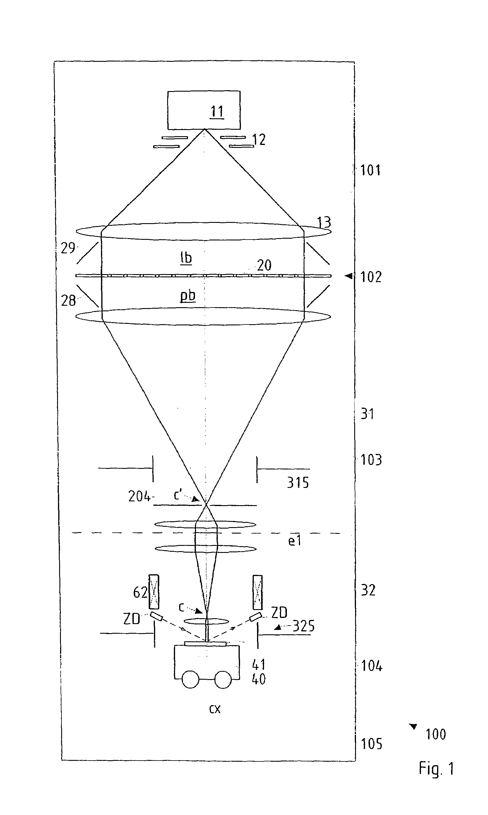
[0046]The preferred embodiments of the invention discussed in the following are suitable for use in the PLM2 apparatus mentioned above which has a two-stage demagnifying projection optical system after the pattern definition device which produces the patterned beam. FIG. 1 shows a schematic overview of the PLM2 apparatus inasmuch as needed for the disclosure of the present invention. For further details about the PLM2 system, the reader is referred to the US-2003-0155534-A1.

[0047]In the following, with reference to FIG. 1 (which was taken, with modifications where appropriate, from the US-2003-0155534-A1) we first discuss the technical background of the PLM2 apparatus and the Pattern Device (PD) device it contains, as far as relevant to the invention. It should be appreciated that the invention is not restricted to the embodiment discussed in the following, which merely represents one of the possible implementations of the invention.

[0048]An overview of a lithographic apparatus empl...


PUM

PropertyMeasurementUnit
depthaaaaaaaaaa
distanceaaaaaaaaaa
opticalaaaaaaaaaa

Abstract

In a particle-optical projection system a pattern is imaged onto a target by means of energetic electrically charged particles. The pattern is represented in a patterned beam of said charged particles emerging from the object plane through at least one cross-over; it is imaged into an image with a given size and distortion. To compensate for the Z-deviation of the image position from the actual positioning of the target (Z denotes an axial coordinate substantially parallel to the optical axis), without changing the size of the image, the system includes a position detector for measuring the Z-position of several locations of the target, and a controller for calculating modifications of selected lens parameters of the final particle-optical lens and controlling said lens parameters according to said modifications.

Description

CROSS REFERENCE TO RELATED APPLICATIONS[0001]This application is a Divisional Application of U.S. patent application Ser. No. 11 / 080,578, filed Mar. 15, 2005, now abandoned which claims priority from Austrian Patent Application No. A 457 / 2004, filed Mar. 15, 2004.FIELD OF THE INVENTION AND DESCRIPTION OF PRIOR ART[0002]The invention relates to the field of particle-optical projection systems and , in particular, to the adjustment of the field position along the optical axis with the actual position of the target in a particle-optical projection system without a change of magnification or image quality. More in detail, the invention relates to the improvement of a particle-optical projection system for imaging a pattern onto a target by means of energetic electrically charges particles in a particle-beam exposure apparatus, adapted to produce, from the pattern positioned at an object plane and represented in a patterned beam of said charged particles emerging from the object plane th...

Claims


Application Information

Patent Timeline
Patent Type & Authority Patents(United States)
IPC IPC(8): H01J37/302H01L21/027G03F7/20G11B7/09H01J37/02H01J37/147H01J37/15H01J37/20H01J37/21H01J37/304H01J37/317
CPCB82Y10/00B82Y40/00H01J37/21H01J37/304H01J37/3177H01J2237/024H01J2237/10H01J2237/216H01J2237/30455H01J37/153
Inventor BUSCHBECK, HERBERTLAMMER, GERTRAUDCHALUPKA, ALFREDNOWAK, ROBERTPLATZGUMMER, ELMARSTENGL, GERHARD
Owner IMS NANOFABTION
Why Eureka
Try Eureka