Device for the correction of the power factor in power supply units with forced switching operating in transition mode

Active Publication Date: 2005-09-20
STMICROELECTRONICS SRL
View PDF6 Cites 87 Cited by
  • Summary
  • Abstract
  • Description
  • Claims
  • Application Information

AI Technical Summary

Problems solved by technology

This has considerable consequences: the current absorbed from the line has peak and effective values that are much greater than in case of the absorption of sinusoidal current, the network voltage is distorted by the almost simultaneous pulsed absorption of all the appliances connected to the network, in the case of three-phase systems the current in the neutral conductor is greatly increased and the energy potential of the system for producing electric energy is poorly used.
In fact, the wave shape of a pulsed current is very rich in odd harmonic distortions that, whilst not contributing to the power returned to the load, contribute t

Method used


Image

  • Device for the correction of the power factor in power supply units with forced switching operating in transition mode
  • Device for the correction of the power factor in power supply units with forced switching operating in transition mode
  • Device for the correction of the power factor in power supply units with forced switching operating in transition mode

Examples


first embodiment

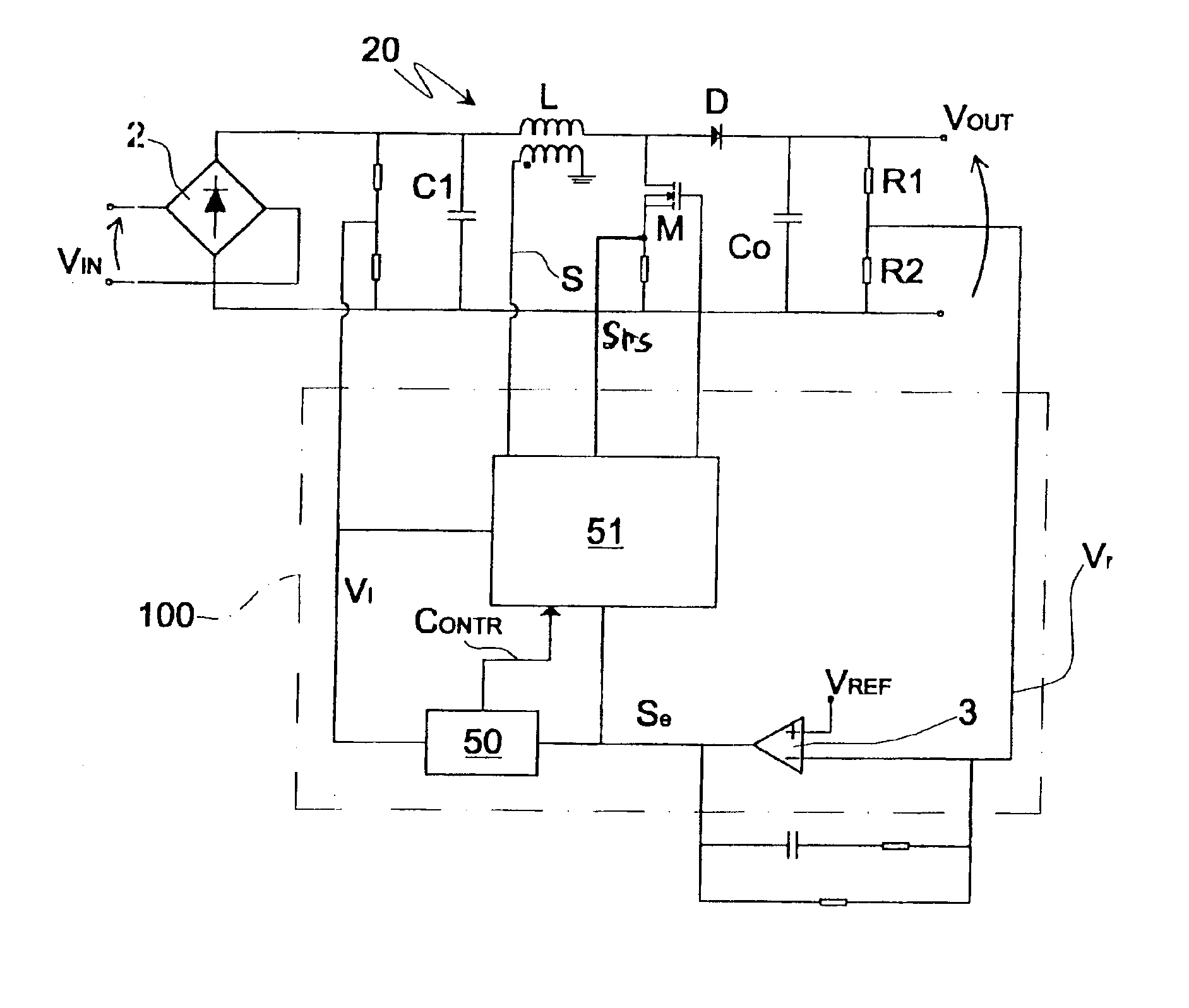
[0036]FIG. 4 shows a PFC for a power supply unit with forced switching operating in transition mode according to the invention; the elements that are the same as the circuit in FIG. 1 will be indicated by the same references. The PFC comprises a boost converter 20 provided with a full-wave diode rectifier bridge 2 that has a network input voltage Vin, a capacitor C1 that has a terminal connected to the diode bridge 2 and the other terminal grounded, an inductor L connected to a terminal of the capacitor C1, a MOS M power transistor with its drain terminal connected to a terminal of the inductor L downstream of the latter and having the source terminal connected to a grounded resistance Rs, a diode D with its anode connected to the terminal shared by the inductor L and the transistor M and the cathode connected to a capacitor Co, the other terminal of which is grounded. The boost converter 20 generates a DC output voltage Vout that is greater than the network maximum peak voltage, ty...

second embodiment

[0052]FIG. 9 shows a block diagram of a circuit of a PFC for a power supply unit with forced switching operating in transition mode according to the present invention. Said circuit comprises the block 50 of FIG. 4 and the multiplier 4 that has the input signals Vi and Se the provides the output signal Sm; the signal Contr leaving block 50 is sent to the non-inverting input of the comparator 5.

[0053]The block 50 enables a positive voltage offset to be added to the signal Sm leaving the multiplier 4 only during the instants of time in which the network voltage Vin has a value close to zero. The positive voltage offset is higher the higher is the network voltage Vin and the lower is the output load. The positive voltage offset is created by adding to the signal Sm from the multiplier 4 a small portion of the signal present on one of its inputs, in other words a portion of the signal Vi or a portion of the signal Se so as to obtain the signal Contr that is sent to the non-inverting inpu...


PUM


Abstract

A device for the correction of the power factor in power supply units with forced switching operating in transition mode is described. The device comprises a converter and a control device coupled to said converter so as to obtain from an alternating network input voltage a regulated output voltage on the output terminal. The converter comprises a power transistor and the control device comprises a pilot circuit suitable for determining the period of switched-on time and the period of switched-off time of said power transistor and control means coupled to said pilot circuits and with said converter and which are capable of prolonging said period of switched-on time of the power transistor at the instants of time in which the alternating network voltage substantially assumes the value zero.

Description

CROSS-REFERENCE TO RELATED APPLICATIONS[0001]This application is related to U.S. patent app. Ser. No. 10 / 633,322 entitled “DEVICE FOR THE CORRECTION OF THE POWER FACTOR IN POWER SUPPLY UNITS WITH FORCED SWITCHING OPERATING IN TRANSITION MODE,” which was filed on the same day as the present application and which is incorporated by reference.PRIORITY CLAIM[0002]This application claims priority from European patent application No. 02425510.1, filed Aug. 1, 2002, and European patent application No. 02425509.3, filed Aug. 1, 2002, which are incorporated herein by reference.TECHNICAL FIELD[0003]The present invention generally refers to a device for the correction of the power factor in power supply units with forced switching operating in transition mode.BACKGROUND[0004]These devices are generally used for the active correction of the power factor (PFC) for power supply units with forced switching used in common electronic appliances such as computers, televisions, monitors, etc and to po...

Claims


Application Information

Patent Timeline
IPC IPC(8): H02M1/00H02M1/42
CPCH02M1/4225Y02B70/126Y02B70/10
Inventor FAGNANI, MAUROPIDUTTI, ALBINOADRAGNA, CLAUDIO
Owner STMICROELECTRONICS SRL
Why Eureka
Try Eureka