Touch screen structure to prevent image distortion

a touch screen and image technology, applied in the field of liquid crystal display panels with touch panels, can solve the problems of distortion still occurring, image distortion, and different amounts of light deterioration, so as to minimize local image distortion

Inactive Publication Date: 2005-04-05
LG DISPLAY CO LTD
View PDF4 Cites 87 Cited by
  • Summary
  • Abstract
  • Description
  • Claims
  • Application Information

AI Technical Summary

Benefits of technology

Accordingly, it is an object of the present invention to provide a liquid crystal display panel mounted with a touch panel ...

Problems solved by technology

Further, the amount of distortion varies depending on the position of the pressurized point.
As a result, amounts of light deterioration and image distortion are different according to the position of the pressurized point.
However, distortion still occurs even if the balls spacers are more...

Method used


Image

  • Touch screen structure to prevent image distortion
  • Touch screen structure to prevent image distortion
  • Touch screen structure to prevent image distortion

Examples


first embodiment

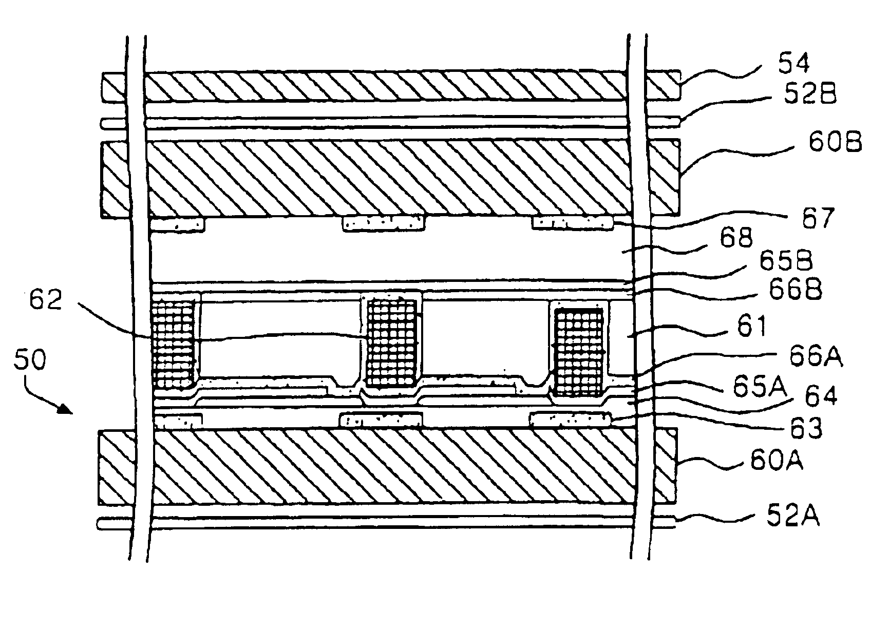
FIG. 6 shows a liquid crystal display panel 50 according to the present invention. The liquid crystal display panel 50 includes lower and upper polarizing sheets 52A and 52B. A touch panel 54 is disposed above the upper polarizing sheet 52B.

Lower and upper glass substrates 60A and 60B are positioned above and below the lower and upper polarizing sheets 52A and 52B, respectively. Gate lines 63, insulating film 64, pixel electrodes 65A, and a first orientation film 66A are sequentially provided above the lower glass substrate 60A. Below the upper glass substrate 60B, black matrix 67, color filter 68, a common electrode 65B, and a second orientation film 66B are also sequentially provided.

Patterned spacers 62 and a liquid crystal material 61 are disposed between the first and second orientation films 66A and 66B. The patterned spacers 62 are formed by photolithographic methods over the pixel electrodes 65A before the first orientation film 66A is formed. The patterned spacers 62 are ma...

second embodiment

FIG. 10 is a sectional view of a combined touch panel and liquid crystal display panel according the present invention. In this embodiment, a polarizing sheet is made to be a part of a touch panel 73. In FIG. 10, the liquid crystal display panel 50 is the same as shown in FIG. 6 except that the display panel 50 does not include the upper polarizing sheet. That is, the liquid display panel 50 of FIG. 10 includes the upper glass substrate 60B and the lower polarizing sheet 52B. Because the parts of the liquid display panel 50 have been described above, detailed discussion of the display panel 50 is omitted.

As shown in FIG. 10, the touch panel 73 is mounted above the upper glass substrate sheet 52B. In this second embodiment, an upper polarizing sheet 75 is made to be a part of the touch panel 73 as shown in FIG. 11. This simplifies the structure of the liquid crystal display panel 50 of FIG. 10.

FIG. 11 is a detailed view of the touch panel 73 of FIG. 10. As shown, the touch panel 73 i...

third embodiment

In this third embodiment, the touch panel 78 and the liquid crystal display panel 50 are integrated with each other by removing the lower glass sheet. Accordingly, the integrated structure of the liquid crystal display panel 50 and the touch panel 78 is made simpler.

FIG. 13 shows a liquid crystal display panel according to a fourth embodiment of the present invention. The fourth embodiment is like the third embodiment, except that the touch panel is capacitive. Because of the integration, the entire structure is made simpler.

As before, the detailed discussion of the liquid crystal display panel 50 is omitted. As shown, the capacitive touch panel 83 is integrated on top of the upper glass substrate 60B. The touch panel 83 includes a transparent electrode layer 84 formed on an upper glass substrate 60B and a polarizing sheet 85 disposed on the transparent electrode layer 84. Like other capacitive touch panels, varying capacitance is detected at the pressurized points and a correspondi...


PUM


Abstract

A touch panel-mounted liquid crystal panel minimizes picture distortion upon driving of the touch panel. In the liquid crystal panel, a lower glass substrate has switching devices provided in the vicinity of intersections between data lines and gate lines. An upper glass substrate has a black matrix joined to it. Patterned clusters of spacers are positioned at an area corresponding to the black matrix in such a manner to enlarge its contact area with the upper glass substrate, thereby keeping a uniform distance between the upper and lower glass substrates. The enlarged contact area allows the patterned clusters of spacers to sufficiently absorb a pressure load of a finger or a stylus pen. Accordingly, uniform distance between the upper and lower glass substrates is maintained even upon driving the touch panel. As a result, light deterioration and local image distortion is prevented or minimized.

Description

BACKGROUND OF THE INVENTION1. Field of the InventionThis invention relates to a liquid crystal display panel, and more particularly to structures within a liquid crystal display panel with a touch panel to minimize light deterioration and image distortion.2. Description of the Related ArtA conventional liquid crystal display panel controls a light transmissivity of liquid crystal cells to display a picture. Liquid crystal cells are formed between two glass substrates. Each liquid crystal cell responds to a video signal, i.e. a pixel signal, to control the transmitted light quantity.Such a liquid crystal display panel maybe mounted with a touch panel to be used as an input device. A user touches the touch panel through a stylus or a finger to input instructions or information. The touch panel generates a voltage or current signal corresponding to a position where the touch panel is touched.The touch panel can be either a capacitive or a resistive type. FIG. 1 shows a liquid crystal d...

Claims


Application Information

Patent Timeline
IPC IPC(8): G09G3/36G02F1/133G02F1/1335G02F1/1339G06F3/033G06F3/041
CPCG06F3/0412G02F1/13394G02F1/13338G02F1/133512G06F3/045
Inventor AHN, YOUNG SOOJEONG, YUN CHEOLOH, YOUNG JIN
Owner LG DISPLAY CO LTD
Why Eureka
Try Eureka