Determination of susceptibility-induced magnetic field gradients by magnetic resonance

a magnetic field gradient and susceptibility-induced technology, applied in the field of magnetic resonance imaging, can solve the problems of time-consuming optimization procedures and laborious procedures, and achieve the effects of facilitating susceptibility imaging, optimal positive contrast, and positive susceptibility contras

Inactive Publication Date: 2010-01-07
KONINKLIJKE PHILIPS ELECTRONICS NV
View PDF2 Cites 5 Cited by
  • Summary
  • Abstract
  • Description
  • Claims
  • Application Information

AI Technical Summary

Benefits of technology

[0007]Therefore, it is readily appreciated that there is a need for an improved device for magnetic resonance imaging for the generation of images with positive (bright) susceptibility contrast. It is consequently an object of the invention to provide an MR device that enables suscept

Problems solved by technology

A drawback of this known technique is that in order to obtain optimal positive image contrast, either prior knowledge about the streng

Method used


Image

  • Determination of susceptibility-induced magnetic field gradients by magnetic resonance
  • Determination of susceptibility-induced magnetic field gradients by magnetic resonance
  • Determination of susceptibility-induced magnetic field gradients by magnetic resonance

Examples


Embodiment Construction

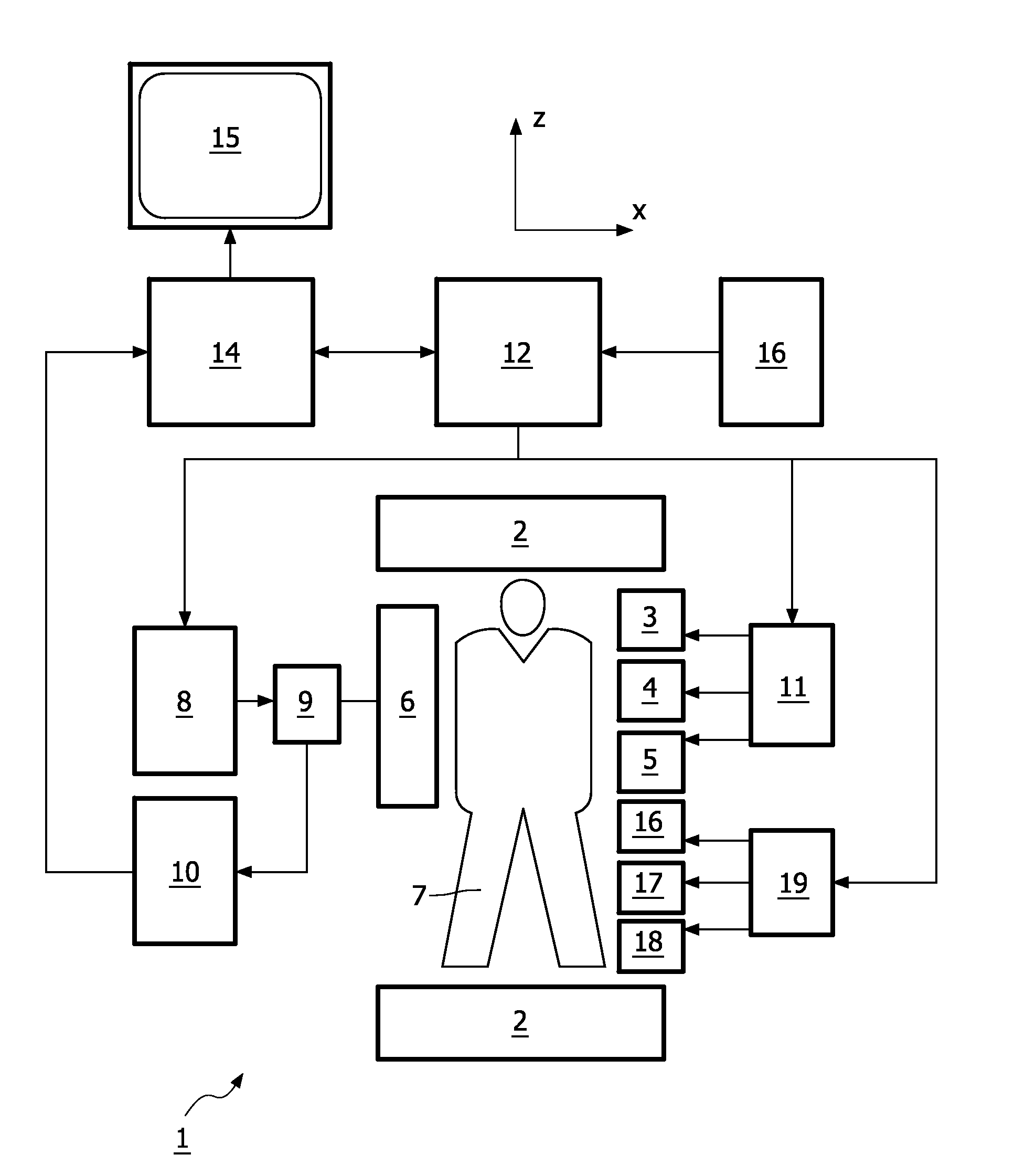
[0028]In FIG. 1 an MR imaging device 1 in accordance with the present invention is shown as a block diagram. The apparatus 1 comprises a set of main magnetic coils 2 for generating a stationary and substantially homogeneous main magnetic field and three sets of gradient coils 3, 4 and 5 for superimposing additional magnetic fields with controllable strength and having a gradient in a selected direction. Conventionally, the direction of the main magnetic field is labelled the z-direction, the two directions perpendicular thereto the x- and y-directions. The gradient coils 3, 4 and 5 are energized via a power supply 11. The imaging device 1 further comprises an RF transmit antenna 6 for emitting radio frequency (RF) pulses to a body 7. The antenna 6 is coupled to a modulator 9 for generating and modulating the RF pulses. Also provided is a receiver for receiving the MR signals, the receiver can be identical to the transmit antenna 6 or be separate. If the transmit antenna 6 and receiv...


PUM


Abstract

The invention relates to a device for magnetic resonance imaging of a body (7). The device (1) comprises means (2) for establishing a substantially homogeneous main magnetic field in the examination volume, means (3, 4, 5) for generating switched magnetic field gradients superimposed upon the main magnetic field, means (6) for radiating RF pulses towards the body (7), control means (12) for controlling the generation of the magnetic field gradients and the RF pulses, means (10) for receiving and sampling magnetic resonance signals, and reconstruction means (14) for forming MR images from the signal samples. In accordance with the invention, the device is arranged to a) generate a series of MR echo signals (20) by subjecting at least a portion of the body (7) to an MR imaging sequence of RF pulses and switched magnetic field gradients, b) acquire the MR echo signals for reconstructing an MR image data set (21) therefrom, c) calculate a gradient map (22) by computing echo shift parameters (SPx, SPy, SPz) from subsets of the MR image data set, the echo shift parameters (SPx, SPy, SPz) indicating magnetic field gradient induced shifts of the echo positions in k-space, wherein each subset comprises a number (n) of spatially adjacent pixel or voxel values of the MR image data set (21).

Description

FIELD OF THE INVENTION[0001]The invention relates to a device for magnetic resonance imaging of a body placed in an examination volume.[0002]Furthermore, the invention relates to a method for MR imaging and to a computer program for an MR device.BACKGROUND OF THE INVENTION[0003]In magnetic resonance imaging (MRI) pulse sequences consisting of RF pulses and switched magnetic field gradients are applied to an object (a patient) placed in a homogeneous magnetic field within an examination volume of an MR device. In this way, phase encoded magnetic resonance signals are generated, which are scanned by means of RF receiving antennas in order to obtain information from the object and to reconstruct images thereof. Since its initial development, the number of clinically relevant fields of application of MRI has grown enormously. MRI can be applied to almost every part of the body, and it can be used to obtain information about a number of important functions of the human body. The pulse se...

Claims


Application Information

Patent Timeline
IPC IPC(8): G06K9/00
CPCG01R33/243G01R33/281G01R33/286G01R33/56536G01R33/48G01R33/5601G01R33/3875
Inventor DAHNKE, HANNESSCHAEFFTER, TOBIASVAN DER MEULEN, PETER
Owner KONINKLIJKE PHILIPS ELECTRONICS NV
Why Eureka
Try Eureka