Patterned chemical sensor having inert occluding layer

a chemical sensor and inert layer technology, applied in the direction of filtration separation, separation processes, instruments, etc., can solve the problems of color change in the sensor portion, and achieve the effect of clear distinction, clear contrast, and easy discernibility

Active Publication Date: 2011-04-28
3M INNOVATIVE PROPERTIES CO
View PDF32 Cites 51 Cited by
  • Summary
  • Abstract
  • Description
  • Claims
  • Application Information

AI Technical Summary

Benefits of technology

[0005]As indicated above, known ESLIs undergo a complete color change that requires the user to distinguish between the original color and the warning color. The present invention overcomes this need to memorize the different colors by providing an occluding layer that is inert to the detection layer. In addition, since the “old” color and the “new” color are placed side-by-side within the same integral film body, the contrast is precisely arranged and is readily discernible, which allows for a variety of images to be produced. Because the occluding layer is inert to the detection layer, the film body does not produce a noticeable color change in response to the presence of the occluding layer, even though it is bound to it. In addition, because the occluding layer is bound to the film body, the chemical that the sensor is responsive to also cannot communicate with the detection layer to cause a color change in that portion of the sensor. Therefore, certain areas of the sensor are masked off to color change and accordingly retain the original sensor color. Thus, when the sensor does undergo a color change, the masked portions of the sensor retain their original color while the other portions assume the warning color. The invention is able to provide a distinct contrast between the original color and the warning color. The user therefore sees two distinct color regions rather than one particular color or a merger of the two. The invention therefore eliminates a need to memorize the difference between the original color and the warning color, and it provides the ability to create a fine line or clear distinction at two different color regions.
[0006]The inert occluding layer that is bound to the film body in accordance with the present invention may be provided in a variety of configurations such that a number of distinctly discernible images can be seen by the user. The ability to bond the inert occluding layer to the film body provides good image resolution since the chemical to-be-detected cannot significantly penetrate between the film body and the occluding layer. The inert occluding layer prevents the detection layer from issuing a false positive in that area of the sensor. Therefore, when the user sees a particular image, they know that the sensor has entered its warning mode. This feature is particularly useful for filter cartridges that have met the end of their service life. Once the warning image has been exhibited by the sensor, the user will know that it is time to replace the filter cartridge.

Problems solved by technology

In addition, because the occluding layer is bound to the film body, the chemical that the sensor is responsive to also cannot communicate with the detection layer to cause a color change in that portion of the sensor.

Method used


Image

  • Patterned chemical sensor having inert occluding layer
  • Patterned chemical sensor having inert occluding layer
  • Patterned chemical sensor having inert occluding layer

Examples


example 1

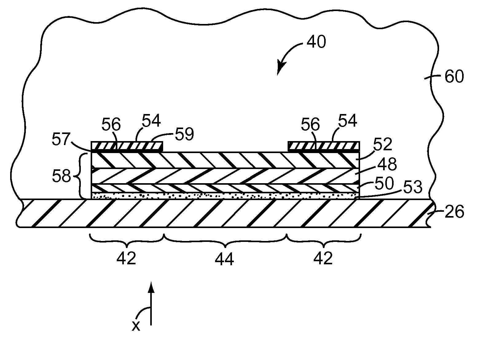
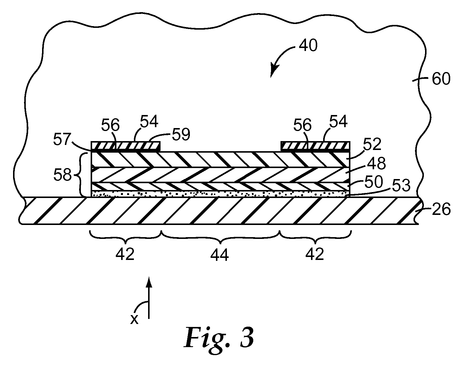
[0067]An example of the invention was made by constructing four layers of material into a sensor film. Layers of the sensor film consisted of: (1) a semi-reflective layer; (2) a porous detection layer; (3) a reflective layer; and (4) an occluding layer.

[0068]Construction of the sensor film began by creating the semi-reflective layer, which was made by coating nickel onto one surface of a polyethylene terephthalate (PET) film (Melinex ST505 clear PET, [Dupont Teijin Films], [Hopewell, Va.]). Nickel was applied to the PET using thermal evaporation under vacuum (base pressure of 10−5 torr). Two Temescal Simba 2 electron beam sources (Edwards Corporation, Tewksbury, Mass.) were used to heat the nickel in graphite crucibles; nickel was deposited until a target optical transparency of 27% was reached, corresponding to a thickness of approximately 10 nm.

[0069]The second layer of the sensor film, which was applied to the Ni coated side of the semi-reflective layer, was a polymer layer of in...


PUM

PropertyMeasurementUnit
effective diameteraaaaaaaaaa
diameteraaaaaaaaaa
diameteraaaaaaaaaa

Abstract

A sensor 40 that detects a chemical such as an organic vapor. The sensor 40 includes a film that has a film body 58 that includes a detection layer 48 and that is responsive to the presence of a chemical by providing a color change. The film also includes an occluding layer 54 that has a first major surface 59 and that is bound to the film body 58 but is inert to the detection layer 48 to preclude the occluding layer 54 and the chemical from causing a color change in the film body 58 in an area 42 normal to the first major surface 59 of the occluding layer 54. A sensor having this construction can provide a distinctly visible image on the sensor, which may be helpful in evaluating the remaining life of a filter cartridge.

Description

[0001]The present invention pertains to a sensor that can display a predetermined visible pattern in response to chemical exposure.BACKGROUND[0002]Sensors are commonly used to detect the presence or absence of a particular chemical. Known sensors have been provided in a variety of forms for achieving this purpose. For example, signs and badges have been developed—see, for example, U.S. Pat. No. 6,284,198 and U.S. Patent Application 2004 / 0223876A1—along with filters, filter cartridges, and breathing masks (respirators) that include chemical indicators—see, for example, U.S. Pat. Nos. 5,323,774, 5,297,544, and 4,684,308. One particular chemical sensor that has been developed is a passive end-of-service-life indicator (ESLI) that has a film-like body. Within the film body is a detection layer that detects the presence of a particular chemical. Examples of film-like passive ESLIs are described in U.S. Patent Publications 2000 / 0063575A1 and 2008 / 0063874A1 to Rakow et al. ESLIs may be tai...

Claims


Application Information

Patent Timeline
Patent Type & Authority Applications(United States)
IPC IPC(8): A62B18/02G01N31/22B01D35/143A62B19/00A62B23/02
CPCA62B18/088G01N31/229A62B19/00
Inventor RAKOW, NEAL A.HOLMQUIST-BROWN, THOMAS W.LINZIE, BRIAN L.HULTEEN, JOHN C.FANSLER, DUANE D.POIRIER, RICHARD J.BHARTI, VIVEK
Owner 3M INNOVATIVE PROPERTIES CO
Why Eureka
Try Eureka