Spot-size effect reduction

a radiographic imaging device and spot size technology, applied in the field of spot size effect reduction, can solve the problems of inability to reduce the spot size of the accelerator to spot size, inability to control the electrons to a very small spot size, and inherent blur of the image generated, so as to improve the image quality of the radiographic imaging device and mitigate the adverse effects of finite spot size on image quality

Inactive Publication Date: 2008-08-26
SIEMENS MEDICAL SOLUTIONS USA INC
View PDF6 Cites 1223 Cited by
  • Summary
  • Abstract
  • Description
  • Claims
  • Application Information

AI Technical Summary

Benefits of technology

[0005]Accordingly, the present invention is directed to apparatus and methods for mitigating the adverse effects of finite spot sizes on image quality, thereby allowing the image quality of the radiographic imaging device to be improved.
[0006]In one embodiment, a radiographic imaging device includes an X-ray source having a finite focal spot characterized by a determined intensity distribution. By first measuring the intensity distribution for the X-ray source, the intensity distribution may subsequently be utilized for improving the image quality of the radiographic imaging device. For instance, the X-ray source may emit a beam of X-ray radiation toward an object. A detector assembly receives at least part of the X-ray radiation after it passes through the object and produces a signal in response to the received radiation. An image processor may then construct an image from the signal generated by the detector using the determined intensity distribution of the X-ray source.
[0008]By utilizing the determined intensity distribution of the X-ray source and inverse filtering the aggregated detector image d(x) from the detector assembly with this intensity distribution scaled for one particular layer of the object, the distortion effects of the finite focal spot size of the X-ray source are mitigated for this layer, allowing novel uses of the resulting aggregated image and ultimately leading to an improved diagnostic value of the measured data. For example, in one embodiment, the measured detector signal d(x) is convolved with an inverse filter gh1−1(x) in the image domain, while in another embodiment, the Fourier transform of d(x), D(u), is multiplied by the inverse of the Fourier transform of gh1(x), 1 / Gh1(u), in the Fourier domain. In this manner, the contribution of one particular layer to the overall projection image is sharpened.

Problems solved by technology

Linear accelerators for radiation therapy, however, were initially not designed as imaging devices, and hence no substantial engineering efforts have been expended to reduce the spot size of those accelerators to spot sizes provided by conventional X-ray tubes.
When a linear accelerator is used as the X-ray source for imaging, it is more difficult to control the electrons to a very small spot size.
The effect of these larger spot sizes is an inherent blurring of the images generated by the radiographic imaging device.

Method used


Image

  • Spot-size effect reduction
  • Spot-size effect reduction
  • Spot-size effect reduction

Examples


Embodiment Construction

[0014]Reference will now be made in detail to the presently preferred embodiments of the invention, examples of which are illustrated in the accompanying drawings.

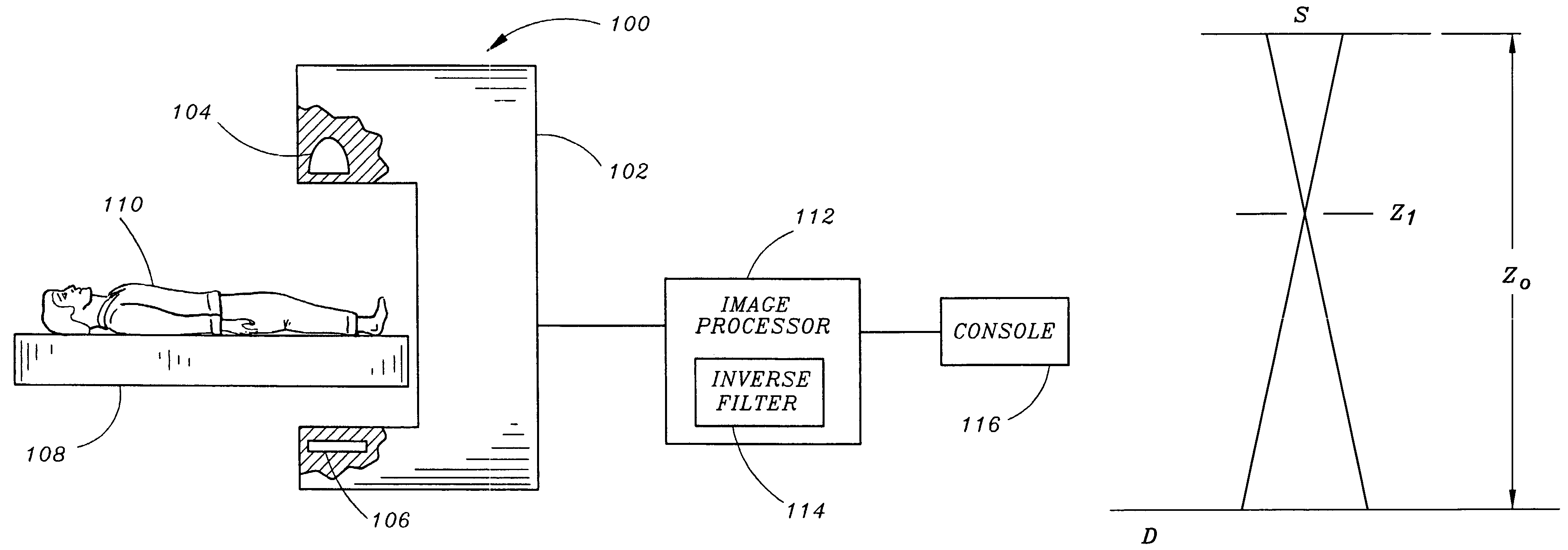
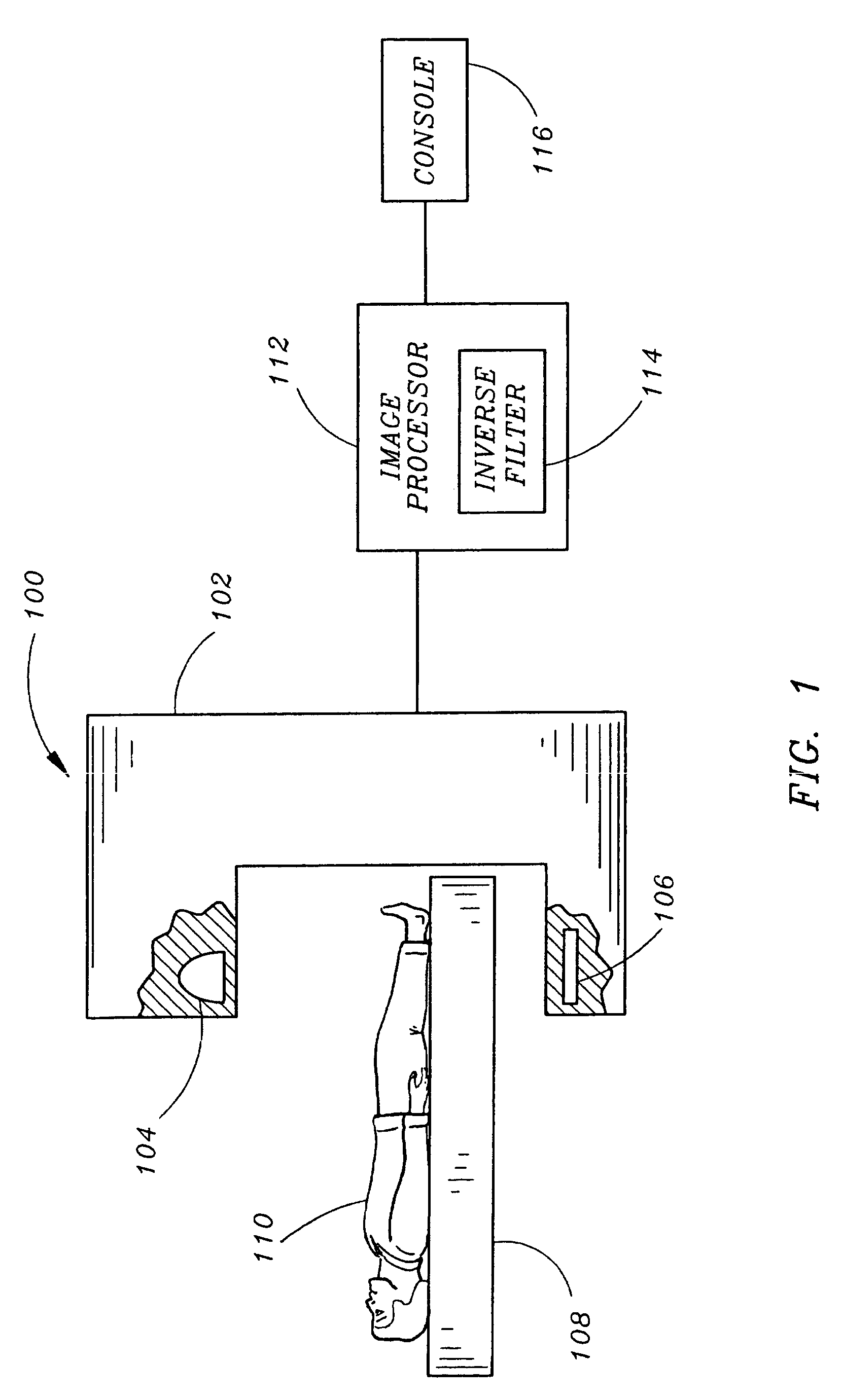
[0015]FIG. 1 illustrates a radiographic imaging device in accordance with an exemplary embodiment of the present invention. The radiographic imaging device 100 includes a scanning unit or gantry 102 supporting an X-ray source 104 and a detector assembly 106, and a patient table 108 for supporting a patient 110 undergoing radiographic imaging. For example, the radiographic imaging device 100 may be a cone beam computed tomography (CBCT) imaging device operating in the megavolt range. The detector assembly 106 includes a plurality of detection elements (e.g., ultra fast ceramic (UFC) detectors, amorphous silicon flat panel detectors, charged coupled device (CCD) detectors, or the like) which convert incident X-rays of varying intensity to analog electrical signals. These analog signals are then amplified and converted to dig...


PUM

PropertyMeasurementUnit
angleaaaaaaaaaa
diametersaaaaaaaaaa
spot sizesaaaaaaaaaa

Abstract

A radiographic imaging device includes an X-ray source having a finite focal spot characterized by a determined intensity distribution. The X-ray source emits a beam of X-ray radiation toward an object. A detector assembly receives at least part of the X-ray radiation after it passes through the object. The detector assembly produces a signal in response to the received radiation. An image processor constructs an image from the signal generated by the detector assembly using the determined intensity distribution of the X-ray source. By inverse filtering the aggregated detector image from the detector assembly, the effects of the finite focal spot size of the X-ray source are mitigated, improving the quality of the resulting image.

Description

BACKGROUND OF THE INVENTION[0001]The present invention relates generally to radiographic imaging devices, and more specifically to a system and method for mitigating the distortion effects of larger spot sizes thereby allowing the image quality of the radiographic imaging device to be improved. The present invention is particularly applicable to X-ray imaging technologies operating in the megavolt (MV) range, such as imaging technologies utilized in radiation therapy.[0002]The quality of X-ray images produced by a radiographic imaging device is determined by a variety of factors. One factor is the size of the focal spot of the source that emanates the X-ray radiation. X-ray tubes for diagnostic applications operating somewhere between 80 kV and 120 kV of incident electron energies have made substantial progress over the years, attaining spot-sizes of much less than 1 mm, which in turn leads to good image quality in diagnostic X-ray imaging.[0003]With the introduction of imaging tech...

Claims


Application Information

Patent Timeline
Patent Type & Authority Patents(United States)
IPC IPC(8): G01N23/04
CPCA61B6/583A61B6/4233A61B6/032A61B6/4085
Inventor BLANZ, WOLF-EKKEHARDBANI-HASHEMI, ALI
Owner SIEMENS MEDICAL SOLUTIONS USA INC
Why Eureka
Try Eureka