Enzyme electrode structure

a technology of enzyme electrodes and electrodes, applied in enzymology, biomass after-treatment, biological testing, etc., can solve the problems of requiring a complicated process in element manufacturing, requiring a lot of labor and time from sampling to dropping

Inactive Publication Date: 2000-06-06
ABBOTT DIABETES CARE INC
View PDF28 Cites 1166 Cited by
  • Summary
  • Abstract
  • Description
  • Claims
  • Application Information

AI Technical Summary

Problems solved by technology

The first method, which comprises dropping the measuring sample directly onto the working electrode, has a problem in that much labor and time are required from the sampling to the dropping.
This method has an advantage that it does not take much labor and time since the measuring sample is directly guided onto the working electrode, but has a disadvantage of requiring a complicated process in element manufacture such as the setting of the sample suction opening part and the air vent hole part on both ends of the cylindrical part.

Method used


Image

  • Enzyme electrode structure
  • Enzyme electrode structure
  • Enzyme electrode structure

Examples


example a1

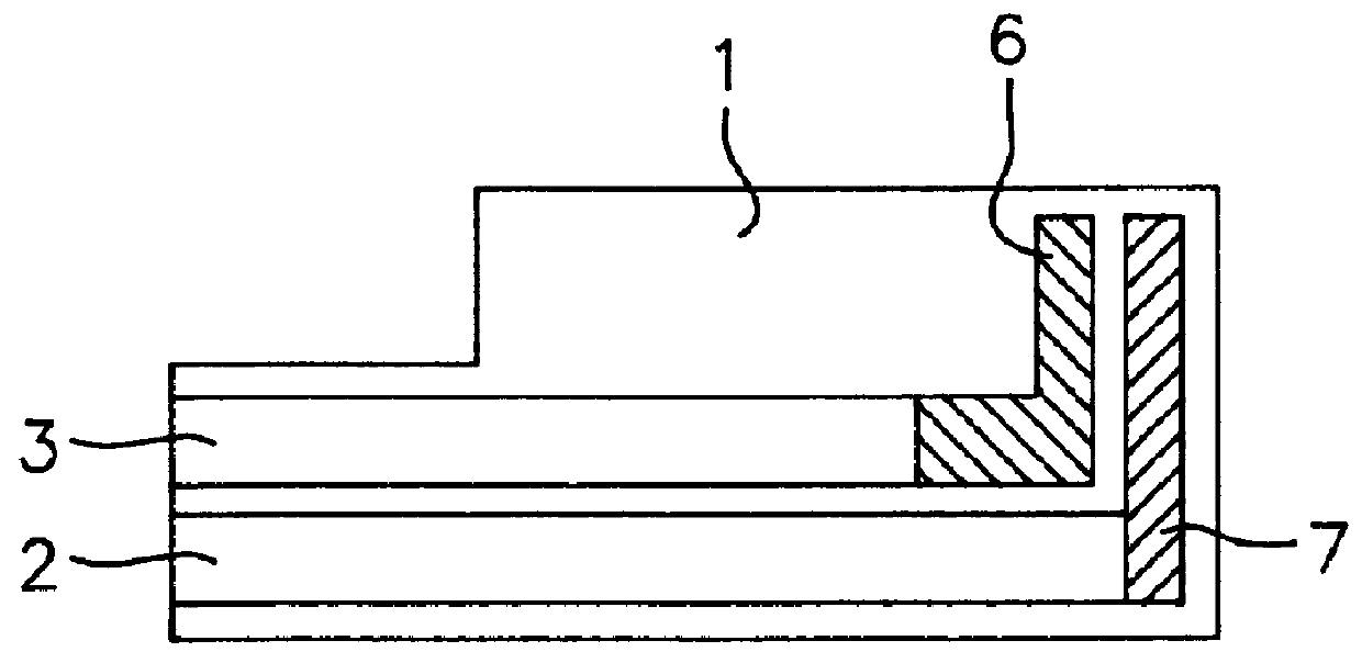
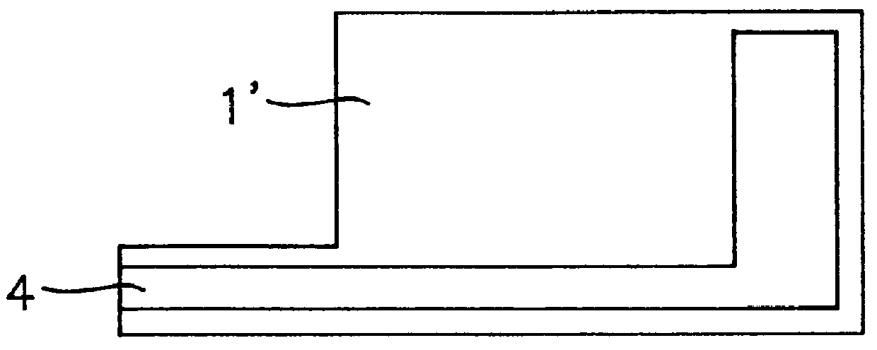
A counter electrode, a working electrode, and a reference electrode lead each of which was made of carbon were formed in a film thickness of 5 .mu.m on a polyethylene terephthalate film (0.25 mm in thickness) by screen printing as the embodiment shown in FIGS. 1-3. A silver paste was printed on the reference electrode lead in a thickness of 5 .mu.m by screen printing followed by baking to form a silver electrode. The silver electrode part was dipped in 0.1M HCl, and silver chloride was formed on the surface by performing a constant current electrolysis for 20 minutes at a current density of 0.6 mA / cm.sup.2 to form a silver / silver chloride reference electrode. For this constant current electrolysis, a potentiogalvanostat (manufactured by Hokuto Denko HA501) was used.

Onto the working electrode within each electrode having such a structure, a mixture consisting of 10 mg of glucose oxidase (165800 unit) and 48 mg of potassium ferricyanide dissolved in 1 ml of phosphoric acid buffer solu...

example b1

Two polyethylene terephthalate bases tapered in one-side ends were prepared, carbon-made electrodes were formed on the respective bases in a thickness of 10 .mu.m by screen printing. Onto one carbon-made electrode, 1.5 .mu.l of a mixture (dopant) consisting of 10 mg of glucose oxidase (165800 unit) and 48 mg of potassium ferricyanide dissolved in 1 ml of water was dropped followed by drying under room temperature condition to form a glucose oxidase-potassium ferricyanide mixture layer (about 100 .mu.m in thickness) as working electrode.

A base A having the thus-obtained mixture layer formed working electrode and a base B having its counter electrode were used, and they were stuck together with a double-sided adhesive tape (Product manufactured by Nitto Denko No. 500; 160 .mu.m in thickness) as the adhesive layer in various embodiments as described below.

(1) The base A having the mixture layer formed working electrode and the base B having the counter electrode are stuck together by t...

example b2

In (1) of Example B1, the glucose aqueous solution was regulated to pH 7.0, and a dopant to which 10 mg of albumin was added was used. The CV value was 4.8%.


PUM

PropertyMeasurementUnit
thicknessaaaaaaaaaa
thicknessaaaaaaaaaa
thicknessaaaaaaaaaa

Abstract

A biosensor comprises a space part for sucking and housing a sample formed of two upper and lower plates, the two plates being stuck together by an adhesive layer, the space part for sucking and housing the sample being constituted so as to be partially opened in the peripheral part and partially closed by the adhesive layer, and has a working electrode having at least glucose oxidase immobilized thereon and a counter electrode on the same plane of the plate.

Description

This invention relates to a biosensor. More specifically, it relates to a glucose biosensor having glucose oxidase immobilized thereon or a biosensor having an oxidoreductase immobilized thereon.PRIOR ARTIn a conventional biosensor having glucose oxidase immobilized on a working electrode, a counter electrode or the counter electrode and a reference electrodes, in addition to the working electrode, are arranged on the same plane of a flat base. In a glucose biosensor having the electrode arrangement as described above, two method are adapted to bring a measuring sample into contact with the working electrode.The first method, which comprises dropping the measuring sample directly onto the working electrode, has a problem in that much labor and time are required from the sampling to the dropping. The second method involves the use of a structure formed of a spacer having a groove arranged on an electrode base and a cover having an air hole further arranged thereon to provide a sample...

Claims


Application Information

Patent Timeline
Patent Type & Authority Patents(United States)
IPC IPC(8): C12Q1/00G01N33/487G01N27/26
CPCC12Q1/005G01N27/3272Y10S435/817
Inventor GOTOH, MASAOMURE, HIROKISHIRAKAWA, HIROSHI
Owner ABBOTT DIABETES CARE INC
Why Eureka
Try Eureka