Power transmission apparatus of motor vehicles

a technology of power transmission apparatus and motor vehicle, which is applied in the direction of electric propulsion mounting, transportation and packaging, gearing, etc., can solve the problems of deteriorating specific fuel consumption, large size of the drive system, and low efficiency of torque transmission, so as to improve transmission efficiency and reduce specific fuel consumption of the vehicl

Inactive Publication Date: 2007-03-06
HITACHI LTD
View PDF42 Cites 54 Cited by
  • Summary
  • Abstract
  • Description
  • Claims
  • Application Information

AI Technical Summary

Benefits of technology

[0008]Accordingly, an object of the present invention is to improve a transmission efficiency, reduce a specific fuel consumption of a vehicle and make a drive system compact, in a power transmission apparatus constituted by a gear change mechanism having an electric rotary machine and a clutch mechanism.

Problems solved by technology

First, in order to reduce a torque shock during changing a gear change ratio, for example, from a first speed to a second speed or from a second speed to a third speed, it is necessary to arrange the electric rotary machine at a drive wheel side to the gear change mechanism. On the contrary, in order to generate power by the engine drive force in the series hybrid manner, it is necessary to arrange the electric rotary machine in the engine side to the gear change mechanism. Accordingly, in order to prevent the gear change shock and also improve the gear change performance, at least two or more electric rotary machines are required, resulting in a problem that the drive system becomes a large size.
Second, since a torque transfer mechanism of the engine output shaft to an electric rotary machine output shaft is complex, an efficiency of torque transmission is low.
Third, since the drive system is so constituted that the electric rotary machine is driven by the engine, an inertia torque of the rotor of the electric rotary machine is exerted on the engine side as a load. Thus, during running under the engine drive, in order to correctly execute an acceleration command from the driver, it is necessary to generate an additional torque for canceling the inertia torque in the engine side as well as the torque corresponding to the acceleration command. This poses a problem that the specific fuel consumption is deteriorated in order to improve a driving performance.

Method used


Image

  • Power transmission apparatus of motor vehicles
  • Power transmission apparatus of motor vehicles
  • Power transmission apparatus of motor vehicles

Examples


first embodiment

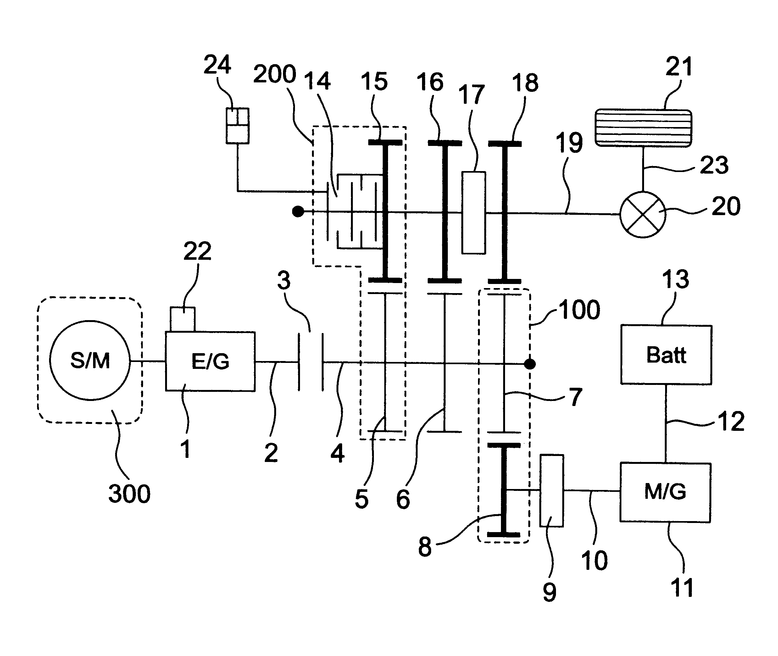
[0027]FIG. 1 is a schematic view showing a whole drive system of motor vehicles according to the invention. Reference numerals 1 and 1101 denote an engine and 11 and 1111 a motor generator which outputs a kinetic energy by an electric energy provided from a battery 13 over line 12 and which converts an applied kinetic energy into an electric energy to store into the battery 13. Reference numerals 21 and 1121 denote a wheel and 23, 923 and 1123 a wheel axle connected to a final gear 20, 920 and 1120.

[0028]Reference numerals 5, 805, 905 and 1105 denote a gear generally called a high speed drive gear, and 15, 815, 915 and 1115 a gear generally called a high speed driven gear which engages with the high speed drive gear 5. The high speed drive gear 5 is fixed on a transmission input shaft 4, 1104.

[0029]Reference numerals 6, 806, 906 and 1106 denote a gear generally called a low speed drive gear, and 16, 816, 916 and 1116 a gear generally called a low speed driven gear which engages with...

second embodiment

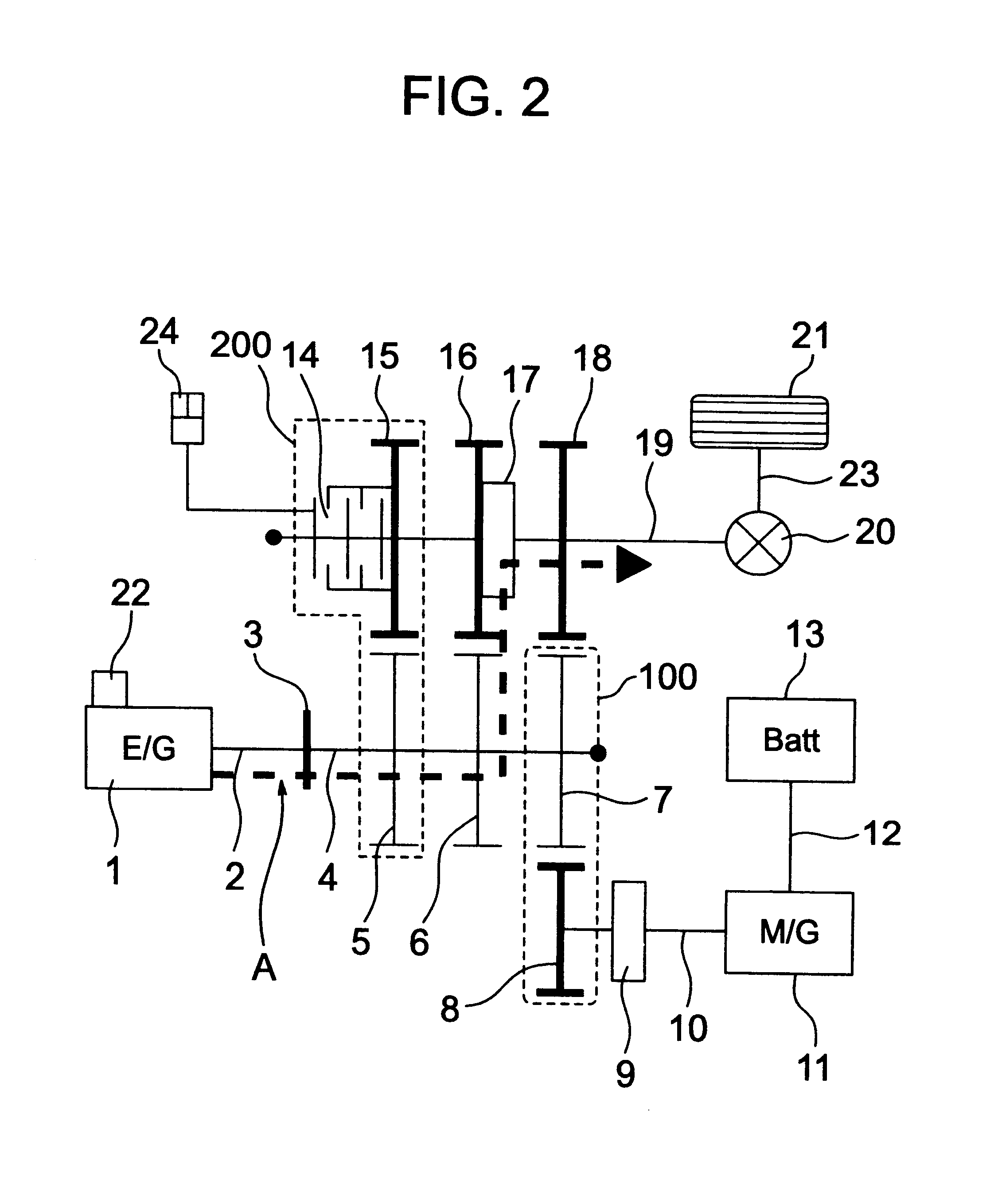
[0053]FIG. 5 is a schematic view of a whole of an automobile system according to the invention. This system corresponds to a structure in which a motor generator dog clutch 9b is arranged in a side of the transmission input shaft 4 and a middle speed drive gear 7b is accordingly arranged so as to freely rotate with respect to the transmission input shaft 4, in the structure shown in FIG. 1. Further, a motor generator driven gear 8 is fixed to the motor generator output shaft 10. The other structures are the same as those shown in FIG. 1, the same reference numerals as those in FIG. 1 are provided to the same elements in FIG. 5, and a description thereof will be omitted. Further, when employing the structure, there is a disadvantage that the motor generator 11 is rotated in an accompanying manner when running according to the engine 1 in the drive mode No. 9 shown in Table 1, however, it is possible to disengage the motor generator 11 when running according to the engine 1 in the oth...

third embodiment

[0054]FIG. 6 is a schematic view of a whole of an automobile system according to the invention. This system corresponds to a structure in which a low speed multi-plate clutch 27 and a middle speed multi-plate clutch 17c are respectively arranged with respect to the low speed driven gear 16 and the middle speed driven gear 18 in place of the gear change dog clutch 17 and a motor generator multi-plate clutch 9c is arranged in place of the motor generator dog clutch 9, in the structure shown in FIG. 1. Also in this structure, it is possible to realize the same effect as the effect of engaging and disengaging the gear change dog clutch 17 and the motor generator dog clutch 9 shown in FIG. 1. For example, when controlling the low speed hydraulic actuator 25 so as to make the pressing force of the low speed multi-plate clutch 27 maximum, the low speed driven gear 16 and the transmission output shaft 19 are connected so as to become in the same state as the state of setting the gear change...


PUM


Abstract

Disclosed is a power transmission apparatus of motor vehicles which has an engine, a gear change apparatus, an electric rotary machine to which a power is transmitted via the gear change apparatus, and a clutch provided between an input shaft and an output shaft of the gear change apparatus and adjusting a transmission torque between the input shaft and the output shaft.

Description

BACKGROUND OF THE INVENTION[0001]The present invention relates to a structure of a power train system comprising an engine, and electric rotary machine (hereinafter, one primarily used for driving is called an electric motor, one primarily used for generating power and starting an engine is called a power generator and one used for driving and generating power with generally the same frequency of each is called a motor generator) and a gear change mechanism, and more particularly to a power transmission apparatus for improving a transmission efficiency of a power train system.[0002]In view of global environment problems, it becomes important to establish a hybrid control system for motor vehicles, in which a great reduction of specific fuel consumption can be expected.[0003]In JP-A-10-217779, there is disclosed an integrated hybrid power transmission apparatus constituted by a single electric rotary machine, a speed change gear mechanism and a clutch mechanism. The apparatus disclos...

Claims


Application Information

Patent Timeline
Patent Type & Authority Patents(United States)
IPC IPC(8): B60K1/00B60K6/442B60K17/02B60K6/48B60K6/547B60K17/04B60W10/02B60W10/06B60W10/08B60W10/10B60W20/00F16H3/089F16H61/04
CPCB60K6/442B60K6/547B60W10/02B60W10/06B60W10/08B60W10/10B60W20/00B60K6/48Y10T74/19284F16H3/089F16H61/0437Y02T10/6221Y02T10/6234Y02T10/6286Y10S903/945Y10S903/946Y10S903/914Y10S903/917Y10S903/919Y10T477/23Y10T74/19014Y10T74/19242Y02T10/62B60K2006/268B60K17/02F16D25/0638
Inventor SAKAMOTO, HIROSHIMINOWA, TOSHIMICHIKAYANO, MITSUO
Owner HITACHI LTD
Why Eureka
Try Eureka