
One-touch connection and disconnection method and apparatus

a technology of one-touch connection and one-touch disconnection, which is applied in the direction of plasma technique, coupling device connection, electrical apparatus, etc., can solve the problems of increasing the time required to engage and disengage the lead connection, affecting the size of the power supply, and time-consuming use of tools, so as to save both the time required to engage and eliminate the need for tools. , the effect of convenient us

Inactive Publication Date: 2007-04-12
HYPERTHERM INC
View PDF8 Cites 59 Cited by
  • Summary
  • Abstract
  • Description
  • Claims
  • Application Information

AI Technical Summary

Benefits of technology

[0014] In another aspect, the invention relates to a lead for a plasma arc torch. The lead includes an elongated body, a first end, and a second end. A second connector is disposed on the second end of the lead and a locking member causes, upon application of a translational force along a longitudinal axis, engagement of the second connector and a first connector. As described above, applying a linear force to the locking member at an angle relative to the longitudinal axis causes disengagement of the first connector and the second connector. The locking member can include a planar member, can be integral to the first or the second connector. The second connector can be a female connector, can be a male connector, can define a fluid passageway, and / or is optionally configured to prevent flow through the fluid passageway when the second connector is disengaged.
[0022] In another aspect, the invention relates to a method for connecting a torch lead to a power supply for a plasma arc torch. The method includes providing a power supply including a housing, disposing relative to the housing a first connector adapted to mate with a second connector, providing a lead including an elongated body, a first end connected to a torch body, and a second end, disposing on the second end of the lead the second connector defining a fluid passageway and configured to prevent fluid flow through the fluid passageway when the second connector is disengaged from the first connector, and engaging the first connector and the second connector. In one embodiment, the first connector defines a second fluid passageway and is configured to prevent fluid flow through the second fluid passageway when the second connector and the first connector are disengaged.
[0027] In yet another embodiment, a third connector, disposed on the second end of the lead, is capable of engaging a fourth connector by causing a compression force in the fourth connector upon application of a translational force along a second longitudinal axis of the lead. The fourth connector causes, upon application of a depression force along the second longitudinal axis, disengagement of the third connector. In one embodiment, the second connector has a first deformable member adapted to disengage the first connector upon application of a depression force applied along the first longitudinal axis to the second connector and the fourth connector has a second deformable member adapted to disengage the third connector upon application of a depression force applied along the second longitudinal axis to the fourth connector. In one embodiment, during application of the depression force to the second and the fourth connectors, the first deformable member is adapted to disengage the first connector and the second connector upon application of a linear force applied along the longitudinal axis to at least one of the first connector and a second connector and a second deformable member is adapted to disengage the third connector and a fourth connector upon application of a second linear force applied along the second longitudinal axis to at least one of the third connector and a fourth connector. Optionally, at least one of the first connector and a second connector defines a fluid passageway and is configured to prevent flow through the fluid passageway when disengaged.
[0036] The connectors and / or connector assemblies can be engaged and / or disengaged with or without tools. In a tool-free method of connection, the connectors can be engaged or disengaged with one or more of a user's fingers. Because the connectors and the connector assemblies can be engaged and / or disengaged with a user's hands, they are easy to use. The area around the connection assembly does not need to accommodate tools or the range of motion required by tools; rather, the area surrounding the connection assembly must accommodate one or more fingers of an operator. The placement of the connectors and / or connector assembly on the plasma arc torch and / or the power supply is accordingly more flexible than when tools are required. Thus, the lead set saves both time required to engage and / or disengage the connection assembly and reduces and / or eliminates the tools required to perform connection and disconnection tasks as compared to a connection requiring tools. Thus, the connection assembly reduces the time required for, for example, assembly, repair, changing lead size, and changing lead type. In addition, because the number of tools required to engage and / or disengage the connection assembly is reduced and / or eliminated the installation, repair, and change complexity are also reduced. The tool free method avoids over tightened and / or under tightened connections thereby reducing leakage, about the connection assembly, of what is being transported through the leads. Also, the life of the connection assembly is improved. In some embodiments, the connectors and / or the connector assembly are designed for frequent and multiple engagements and disengagements.

Problems solved by technology

Some lead connections require large access areas, which impact power supply size.
Certain connectors must be visible to enable engagement and / or disengagement, which impacts lead placement, space, can necessitate lighting, and can increase the time required to engage and disengage the lead connections.
The use of a tool can be time consuming, the tool can be easily misplaced, and space must be available on the power supply and / or adjacent the connector to accommodate the tool.
Threaded connector fittings can be incorrectly installed and tightened causing wear and / or leaking.
Certain connectors and / or leads leak after multiple or frequent engagements and disengagements.
Otherwise, when a lead is removed from the power supply, fluids, for example liquid and gas, continue to flow through the power supply creating a mess, wasting fluids, and risking a slip and fall hazard.
Even when the fluid flow has been stopped, liquid remaining in a removed liquid lead sometimes spills on, for example, an operator's hands or about the work area risking a safety hazard.
Certain connectors must be visible to enable engagement and / or disengagement, which impacts lead placement, space, can necessitate lighting, and can increase the time required to engage and disengage the lead connections.
The use of a tool can be time consuming, the tool can be easily misplaced, and space must be available on the plasma arc torch and / or adjacent the connector to accommodate the tool.
In addition, previous lead / torch connections require multiple wrench connections, which is time consuming.
Threaded connector fittings can be incorrectly installed and tightened causing wear and / or leaking.
Replacement of the lead set in the field is challenging and time consuming due to the limitations of these prior systems.
Certain connectors and / or leads leak after multiple or frequent engagements and disengagements.

Method used


Image

  • One-touch connection and disconnection method and apparatus
  • One-touch connection and disconnection method and apparatus
  • One-touch connection and disconnection method and apparatus

Examples


Embodiment Construction

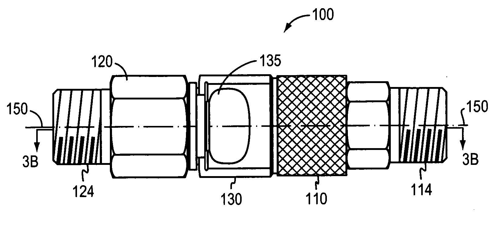
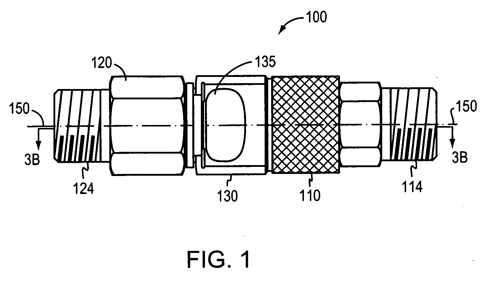
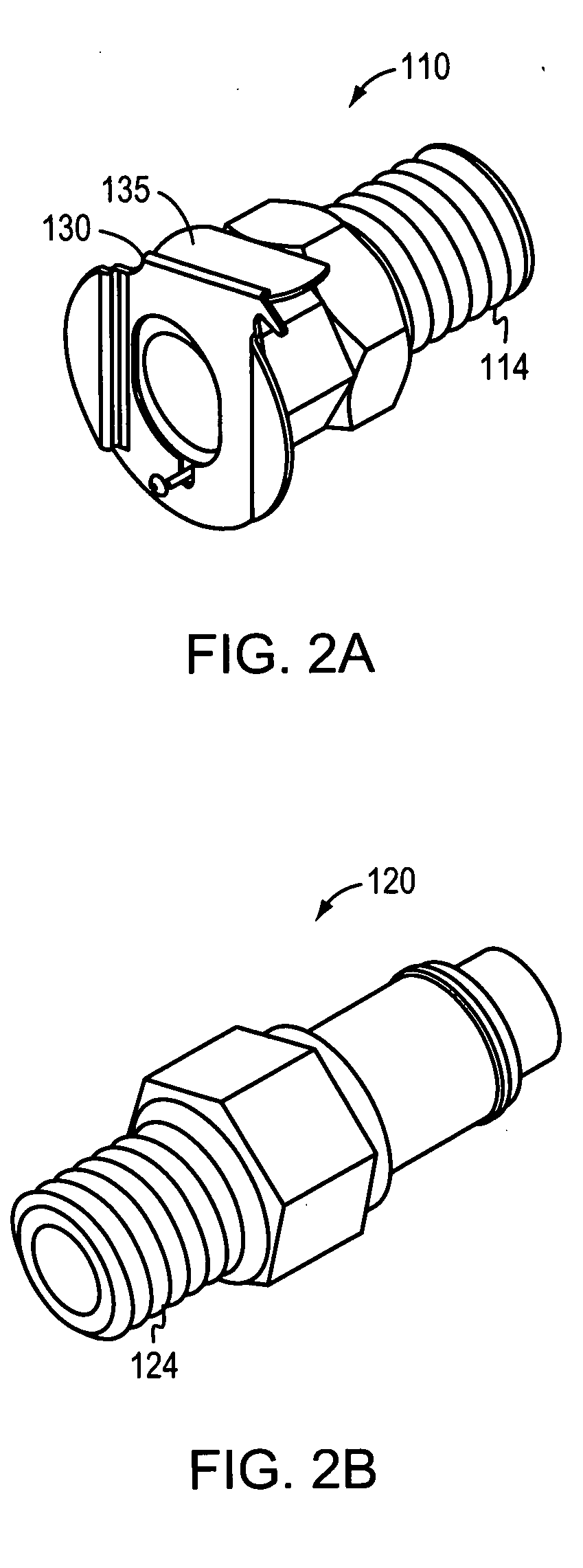
[0061]FIG. 1 illustrates a connector assembly 100 that connects a lead to a power supply for a plasma arc system. Referring also to FIGS. 2A-2B, the connector assembly 100 features a first connector 110 and a second connector 120. The first connector 110 is adapted to mate with the second connector 120 along a longitudinal axis 150. The first connector 110 is, for example, a female connector adapted to receive a mated male connector. A first locking member 130 engages the first connector 110 and the mated second connector 120. Similarly, the first locking member 130 disengages the first connector 110 and the second connector 120. In one embodiment, the first locking member 130 is integral to the first connector 110. Alternatively, a locking member can be integral to the second connector 120 (not shown). In another embodiment, a locking member is separate from both the first connector 110 and the second connector 120 (not shown).

[0062] The first connector 110 termination 114 is thre...


PUM


Abstract

A first connector is disposed on a first end of a lead in a lead set for use with a plasma arc torch. The first connector is capable of engaging a second connector by causing a compression force in a second connector. The second connector compression force is caused by application of a translational force along a longitudinal axis. The second connector causes, upon application of a depression force along the longitudinal axis, disengagement of the first connector. The second causes disengagement of the first connector upon application of a linear force applied along the longitudinal axis to at least one of the first connector and the second connector. The second end of the lead may also be connected to a power supply. Methods for connecting and disconnecting a lead are also disclosed.

Description

RELATED APPLICATION [0001] This application claims the benefit of and priority to and is a continuation-in-part of the U.S. patent application entitled “One Touch Connection and Disconnection Method and Apparatus” filed on Oct. 11, 2005, U.S. Ser. No. 11 / 248,717, the entirety of which is incorporated by reference herein.FIELD OF THE INVENTION [0002] The invention relates generally to a connector for a tool. More particularly, the invention relates to a connector for a plasma arc system. BACKGROUND OF THE INVENTION [0003] Plasma arc torches are widely used in the cutting or marking of metallic materials. A plasma torch generally includes an electrode and a nozzle having a central exit orifice mounted within a torch body, electrical connections, passages for cooling, passages for arc control fluids, and a power supply. Optionally, a swirl ring is employed to control fluid flow patterns in the plasma chamber formed between the electrode and nozzle. The torch produces a plasma arc, a co...

Claims


Application Information

Patent Timeline
Patent Type & Authority Applications(United States)
IPC IPC(8): H01R13/627
CPCH05H1/34H05H1/3423
Inventor CURRIER, BRIAN J.MORRIS, RONALD EDWARD
Owner HYPERTHERM INC
Learn More