Method and/or system for compensating for effects of heat flow and/or air flow through fiberglass insulation

a technology of heat flow and air flow, applied in the direction of heat measurement, building repairs, instruments, etc., can solve the problems of air flow, deception of measurement results, air flow through the wall, etc., and achieve the effect of reducing the amount of hea

Inactive Publication Date: 2006-12-07
KNAUF INSULATION LLC
View PDF23 Cites 38 Cited by
  • Summary
  • Abstract
  • Description
  • Claims
  • Application Information

AI Technical Summary

Benefits of technology

[0003] The insulation of wall cavities is known in the art. For example, it is known to position insulating fiberglass batts in vertical wall cavities of a home or building in order to insulate the wall. Such insulation helps reduce the amount of heat which can escape a

Problems solved by technology

Unfortunately, the standard testing device of FIG. 1 discussed above determines thermal properties of the test sample via steady state or static testing, where there is no air flow (i.e., there is zero air movement introduced into the testing equipment during the testing).
Thus, measurements from such devices can be deceiving as will be explained below, because they do not measure the effects of air flow through the insulation.
When insulation (e.g., fiberglass insulation batt, fiberglass loose-fill, combination/laminate of fiberglass and foam insulation, or the like) is provided in a vertical wall cavity of a home (e.g., betwe

Method used


Image

  • Method and/or system for compensating for effects of heat flow and/or air flow through fiberglass insulation
  • Method and/or system for compensating for effects of heat flow and/or air flow through fiberglass insulation
  • Method and/or system for compensating for effects of heat flow and/or air flow through fiberglass insulation

Examples


Embodiment Construction

[0024] Referring now more particularly to the accompanying drawings in which like reference numerals indicate like parts throughout the several views.

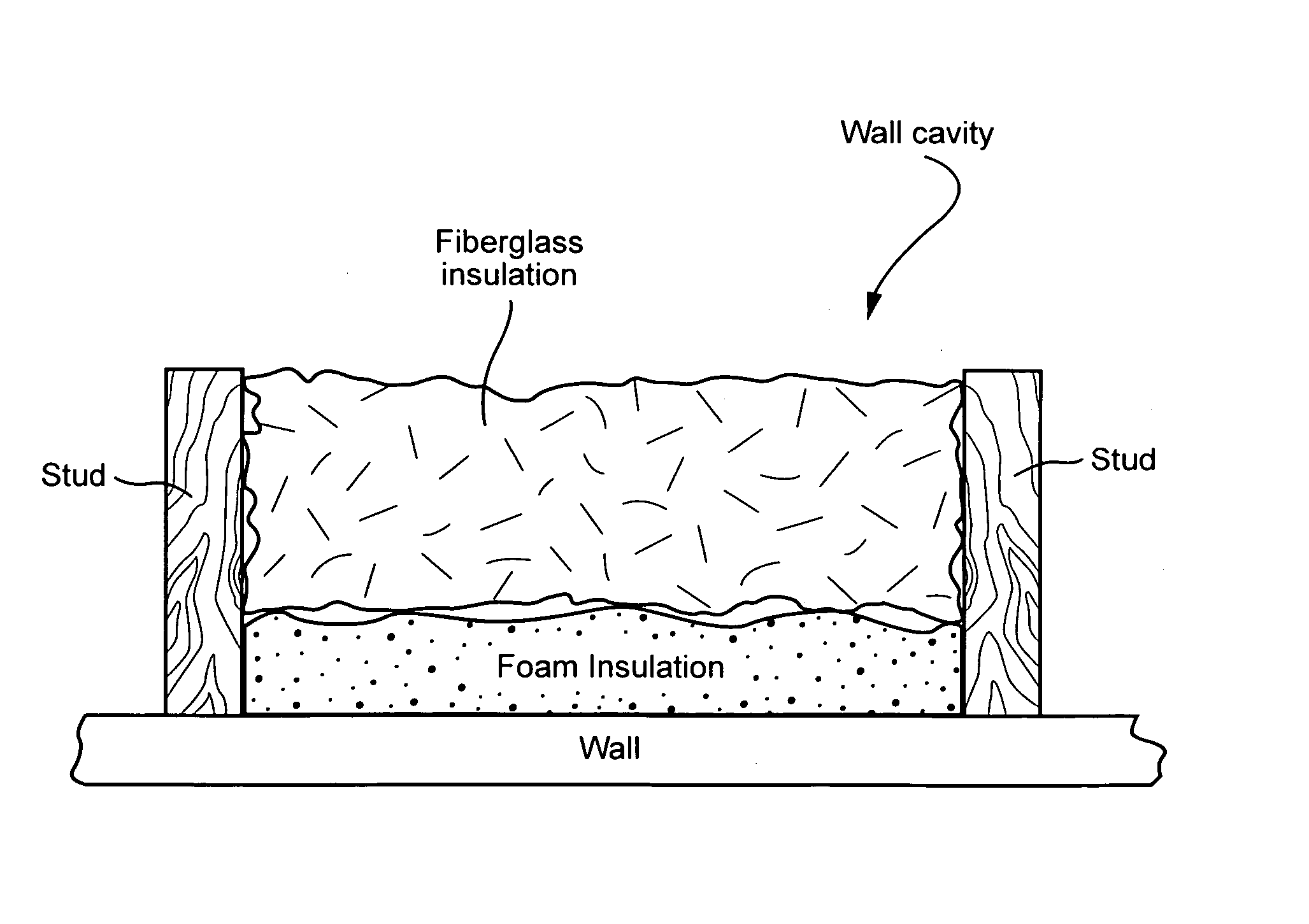
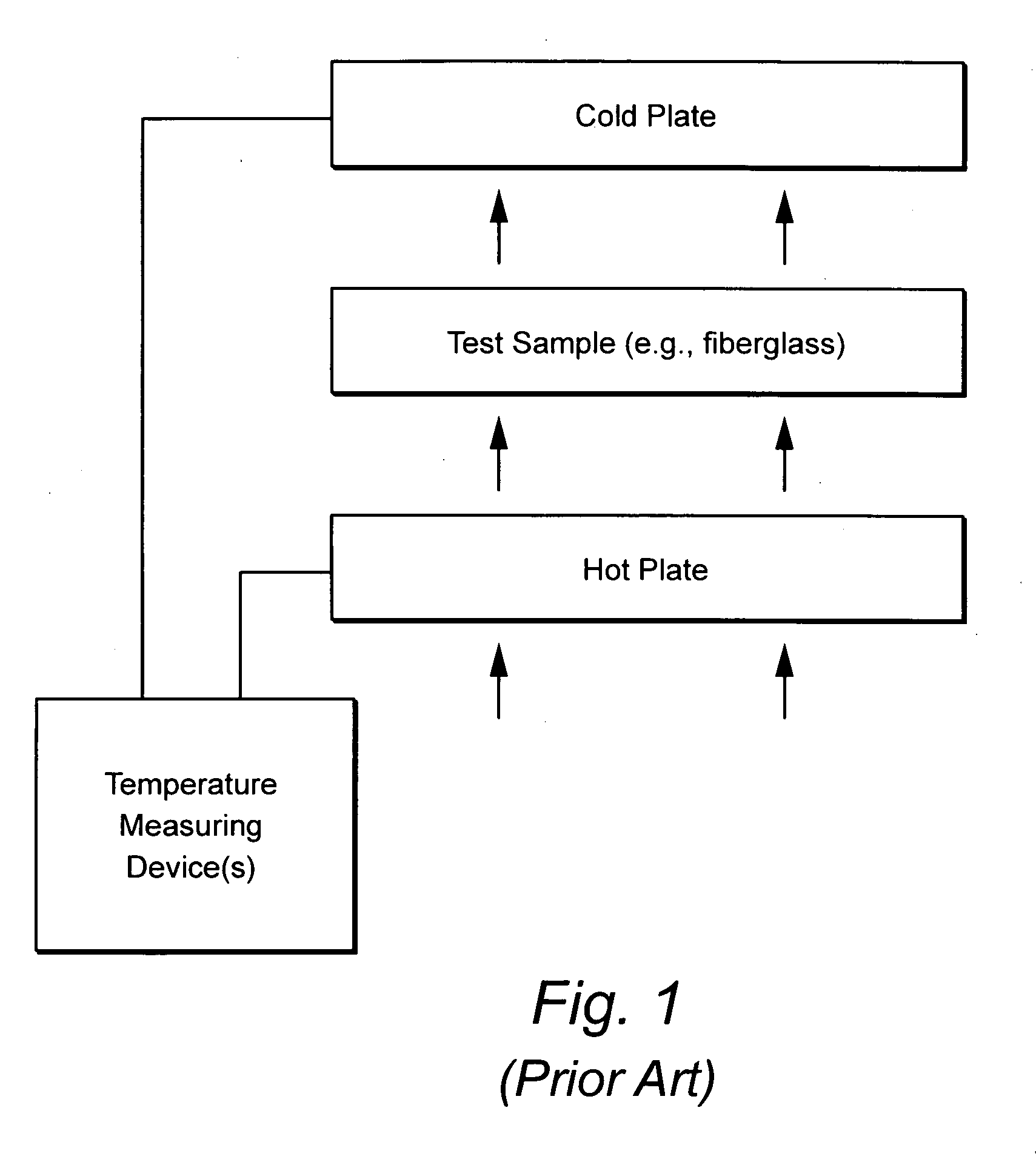
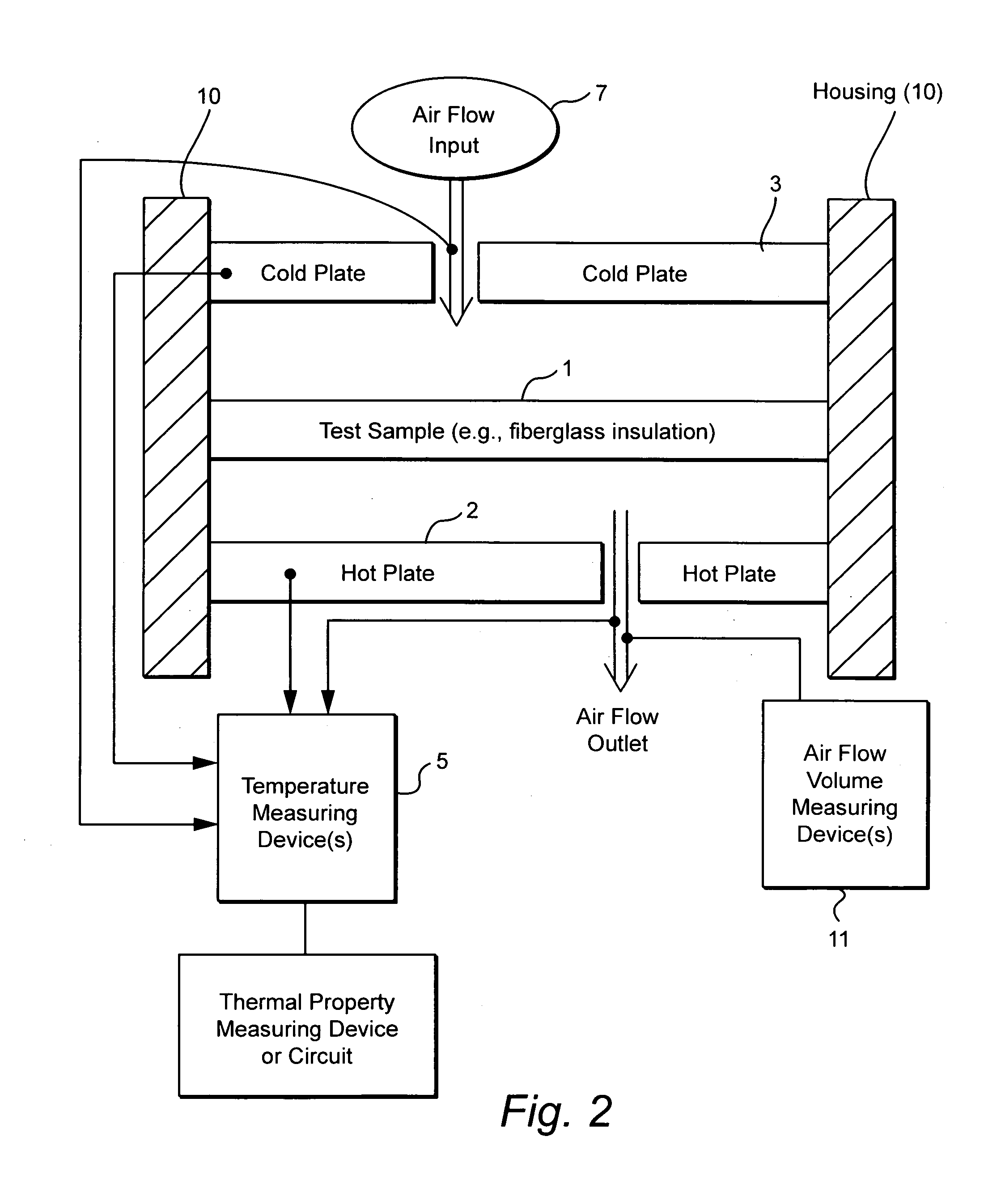
[0025] Certain example embodiments of this invention relate to a method and / or system that compensates for the flow of air through fiberglass insulation. In certain example embodiments, dynamic heat flow meter or the like is provided for measuring the thermal properties of a material (e.g., insulation such as fiberglass inclusive insulation, or any other suitable material) including determining any detrimental effects of air flow therethrough. Once the possible detrimental effects associated with air flow are recognized, the insulation system is adapted (e.g., by providing a foam based insulation in a wall cavity in addition to the fiberglass insulation) to compensate, or substantially compensate, for the effects of air flow through the fiberglass. For instance, a sufficient amount of foam insulation may be provided in the cavity adja...


PUM


Abstract

A method and/or system is provided that compensates for the flow of air through fiberglass insulation. In certain example embodiments, a dynamic heat flow meter or the like is provided for measuring and/or determining any detrimental effects of air flow through insulation such as fiberglass insulation. Once the possible detrimental effects are recognized, an insulation system is adapted (e.g., by providing a foam based insulation in a wall cavity in addition to the fiberglass insulation) to compensate, or substantially compensate, for the effects of air flow through the fiberglass. For instance, a sufficient amount of foam insulation may be provided in a cavity adjacent fiberglass, where the foam blocks or substantially blocks air from flowing through the cavity, thereby compensating for the effects of air flow through fiberglass and permitting the intended R-value to be maintained or substantially maintained.

Description

[0001] This application is a continuation-in-part (CIP) of U.S. Ser. No. 11 / 127,316, filed May 12, 2005, the entire disclosure of which is hereby incorporated herein by reference. [0002] This application relates to a method and / or system that compensates for the flow of air through fiberglass insulation. In certain example embodiments, dynamic heat flow meter or the like is provided for measuring the thermal properties of a material (e.g., insulation such as fiberglass inclusive insulation, or any other suitable material) including any detrimental effects of air flow therethrough. Once the possible detrimental effects are recognized, the insulation system is adapted (e.g., by providing a foam based insulation in a wall cavity in addition to the fiberglass insulation) to compensate, or substantially compensate, for the effects of air flow through the fiberglass. For instance, a sufficient amount of foam insulation may be provided in the cavity adjacent the fiberglass insulation, wher...

Claims


Application Information

Patent Timeline
IPC IPC(8): E04C2/34
CPCG01K17/08G01N25/18G01N25/005
Inventor ROMES, GARY E.YARBROUGH, DAVID W.
Owner KNAUF INSULATION LLC
Why Eureka
Try Eureka