Controller Device of Cooling Fan

a controller device and fan technology, applied in the direction of motor/generator/converter stopper, electronic commutator, dynamo-electric converter control, etc., can solve the problems of large heat generated during device operation, physical limitation of traditional temperature-controlled speed adjustment design of cooling fan, and traditional model that does not meet the current design trend of lightweight and compact electronics, etc., to achieve simple pwm controller device design high rotational speed

Inactive Publication Date: 2007-03-29
LIN TRAIN
View PDF3 Cites 9 Cited by
  • Summary
  • Abstract
  • Description
  • Claims
  • Application Information

AI Technical Summary

Benefits of technology

[0007] The invention is to solve the afore-mentioned problems. The invention utilizes simple PWM controller device design, and directly attaching the PWM controller externally to a cooling fan motor. The driver device internally detects the temperature variation of an electronic element, and drives the fan motor to operate in high rotational speed accordingly. When the temperature of the electronic element is reduced, the fan motor yet remains in high rotational speed. To reduce the rotational speed, a PWM signal is input to the PWM controller device, such that a voltage-drop signal is generated therefrom to drive the fan motor to reduce rotational speed effectively. The PWM controller device functions nearly the same as a MCU, while also reduces manufacturing costs and overall physical size that are suitable for use in compact electronic devices.

Problems solved by technology

Due to high density and high computation power of electronic components, a lot of heat is generated during device operation.
However, the traditional temperature-controlled speed adjustment design of cooling fans are physically limited in size due to the structural nature of the electronic elements and wires, and can not be reduced to less than 6 cm.
Hence, the traditional model does not satisfy the current design trend for lightweight and compact electronics.
Also, the servo control of traditional cooling fan does not reach a fast, stable, and flawless state.
Although the use of a MCU may solve such a problem, the implementation of a MCU means a 2 to 3 times increase in costs as compared to a traditional architecture, and works in no favor to bring down the manufacturing size to less than 6 cm.

Method used


Image

  • Controller Device of Cooling Fan
  • Controller Device of Cooling Fan
  • Controller Device of Cooling Fan

Examples


Embodiment Construction

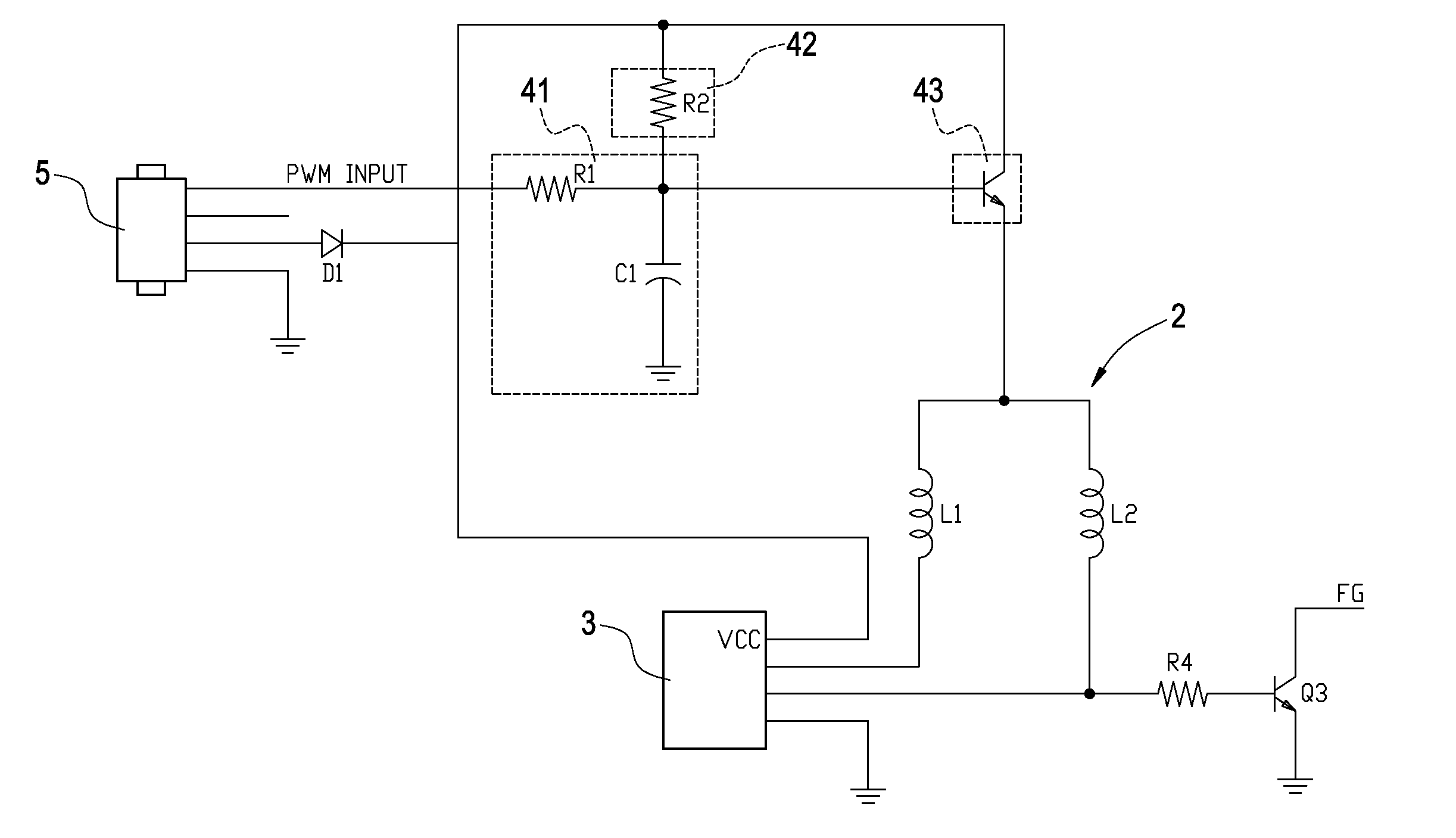
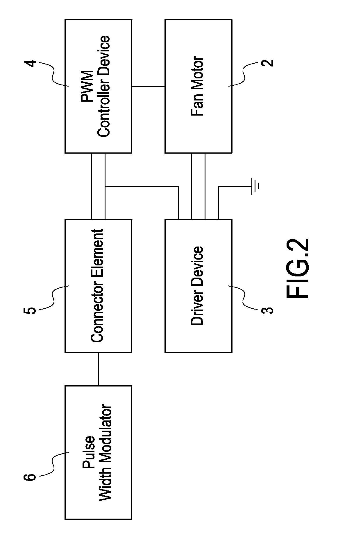
[0014]FIGS. 2 and 3 are schematics illustrating a controller device in a half-wave configuration according to a preferred embodiment of the invention. FIG. 3 is a circuit schematic illustrating a controller device according to a preferred embodiment of the invention. As shown in FIGS. 2 and 3, the controller device of a simple cooling fan includes a fan motor 2, a driver device 3, a PWM controller device 4, and a connector element 5. The driver device 3 is connected to the fan motor 2. The PWM controller device 4 is connected to the fan motor 2 and the driver device 3. The connector element 5 is electrically connected to PWM controller device 4 to input the external PWM signal. The above-mentioned elements collectively form a simple, low-cost externally added PWM controller device to be applied in a cooling fan, allowing the overall size of the cooling fan to be manufactured less than 4 cm, and providing a cooling fan having PWM control capability that is near that of a MCU.

[0015] ...


PUM


Abstract

A PWM controller device of a simple cooling fan includes a fan motor, a driver device, and a PWM controller device. The driver device is electrically connected to the fan motor. The PWM controller device is electrically connected to the fan motor and the driver device. The driver device internally detects the temperature rise variation of the electronic element and drives the fan motor to rotate in high speed. When the fan motor remains in high rotational speed as the temperature of the electronic element decreases, a PWM signal is input to the PWM controller device, which responsively generates a voltage-drop signal to drive the fan motor to its reduce rotational speed. The PWM controller device achieves control similar to that of a MCU, reduces manufacturing costs, and reduces over all physical size of the cooling fan. The invention is suitable for use in compact electronics.

Description

BACKGROUND OF THE INVENTION [0001] 1. Field of the Invention [0002] The present invention relates to a cooling device, and in particular, to an externally connected PWM (Pulse Width Modulation) controller device applicable in a cooling fan. [0003] 2. Description of Prior Art [0004] Current focus in the IT and consumer electronics industry is on the development of electronic gadgetries with multi-functions, high computational power, and compact size. Due to high density and high computation power of electronic components, a lot of heat is generated during device operation. A cooling mechanism is therefore required to prevent overheat and enable proper circuit operation. The cooling fan plays a major role in a cooling mechanism in generating sufficient wind flow to increase heat exchange rates, thereby accomplishing fast heat dissipation. [0005]FIG. 1 shows schematic illustrating the architecture of a traditional cooling fan 1, which includes a fan motor 11, and a fan driver device 12...

Claims


Application Information

Patent Timeline
Patent Type & Authority Applications(United States)
IPC IPC(8): H02P7/06
CPCF04D27/004F04D25/08Y02B30/70
Inventor LIN, TRAIN
Owner LIN TRAIN
Why Eureka
Try Eureka