Method and arrangement for automatic frequency control in a communication system

a communication system and automatic frequency control technology, applied in the field of automatic frequency correction in communication systems, can solve the problems of inability to overcome non-ideal characteristics of the frequency estimator by the loop filter, inability to consider the use of this technique in modern wide-band communication systems, and inability to accept unacceptable response times

Active Publication Date: 2007-06-21
NVIDIA CORP
View PDF5 Cites 51 Cited by
  • Summary
  • Abstract
  • Description
  • Claims
  • Application Information

AI Technical Summary

Problems solved by technology

The loop filter can influence characteristics of the overall loop such as response time and output frequency variance; however, the loop filter can not overcome non-ideal characteristics in the frequency estimator.
For example, a frequency estimator with a very high variance may require an impractically narrow loop filter which results in unacceptable response times. Also, if the frequency estimate is biased, the control loop will not tend to zero steady-state error, but will reach a steady state condition with a residual frequency error which can not be removed by any loop filter characteristic.
An unmodulated carrier signal represents a narrow band signal and can not benefit from the advantages of frequency diversity offered by wide-band modulated signals; hence, the use of this technique is cannot be considered for modern wide-band communication systems such as wide-band code-division-multiple access (W-CDMA) systems.
This technique is still a narrow band solution and not appropriate for wideband modulation systems.
However, neither of the above schemes can obtain the frequency correction accuracy required to have minimal impact on the error rate of the received data in all channel configurations of a TDD UMTS system.

Method used


Image

  • Method and arrangement for automatic frequency control in a communication system
  • Method and arrangement for automatic frequency control in a communication system
  • Method and arrangement for automatic frequency control in a communication system

Examples


Embodiment Construction

)

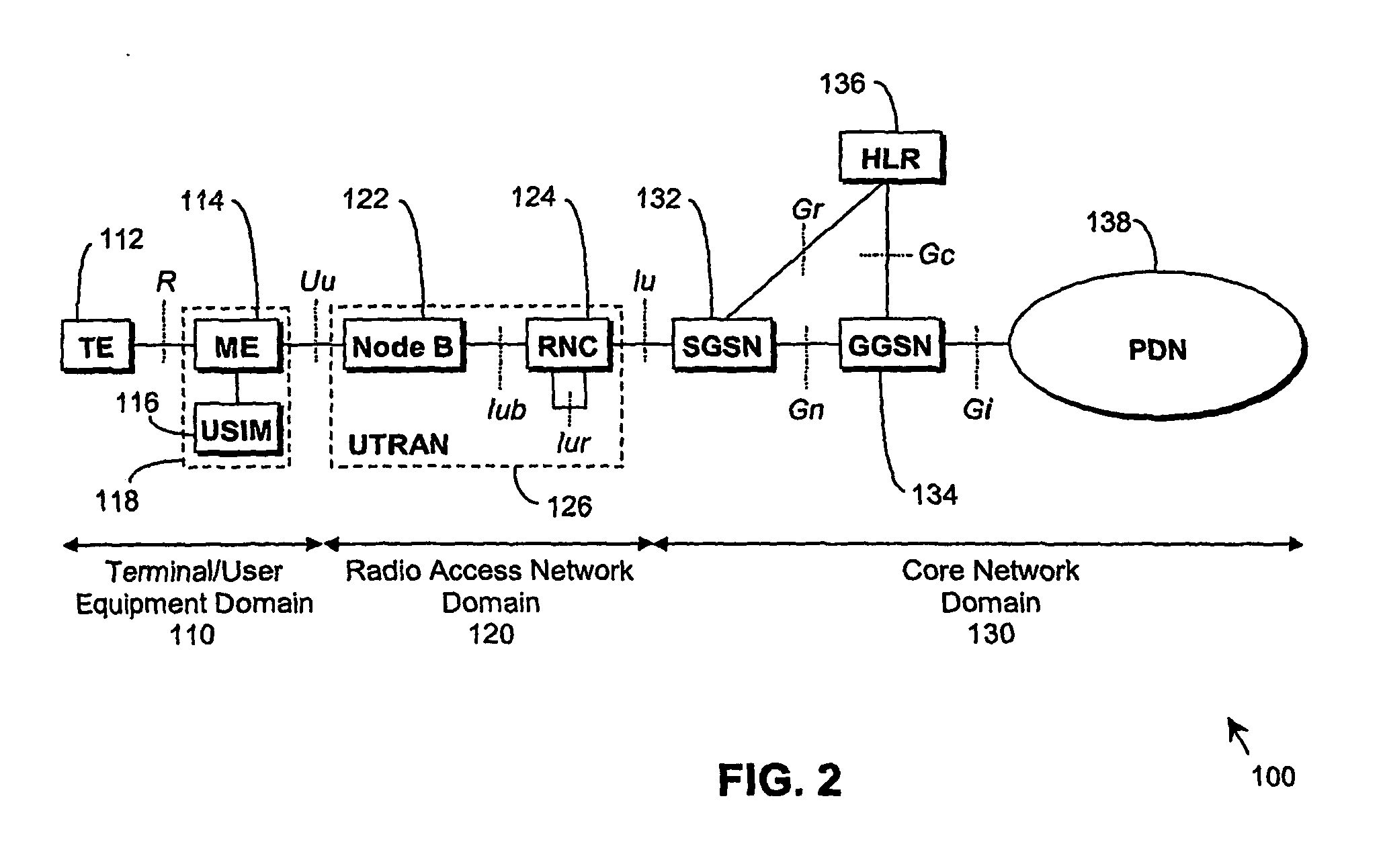
[0029] The following preferred embodiment of the present invention will be described in the context of a UMTS Radio Access Network (UTRAN) system operating in TDD mode. Referring firstly to FIG. 2, a typical, standard UMTS Radio Access Network (UTRAN) system 100 is conveniently considered as comprising: a terminal / user equipment domain 110; a UMTS Terrestrial Radio Access Network domain 120; and a Core Network domain 130.

[0030] In the terminal / user equipment domain 110, terminal equipment (TE) 112 is connected to mobile equipment (ME) 114 via the wired or wireless R interface. The ME 114 is also connected to a user service identity module (USIM) 116; the ME 114 and the USIM 116 together are considered as a user equipment (UE) 118. The UE 118 communicates data with a Node B (base station) 122 in the radio access network domain 120 via the wireless Uu interface. Within the radio access network domain 120, the Node B 122 communicates with a radio network controller (RNC) 124 via the ...


PUM


Abstract

An arrangement (900), method and unit for AFC in a communication system (100) having: a frequency estimator (980) producing a decision-directed frequency estimate from a received signal; and an AFC loop receiving the decision-directed frequency estimate and performing therewith frequency control. The AFC process may use a CRC-decision directed frequency estimate as the final stage in a multi-stage AFC process (preceded by SCH- and midamble-derived frequency estimate stages), such that a verified received data sequence is used to re-construct a local copy of the ideal received data symbols expected at the output of a detector. This local copy is then correlated with the actual detector output and the results used to estimate the frequency error present on the received signal. The AFC process is inherent suited for discontinuous receive (DRX) applications. This provides the advantage of allowing required frequency correction accuracy to have minimal impact on the error rate of the received data in various channel configurations.

Description

FIELD OF THE INVENTION [0001] This invention relates to automatic frequency correction (AFC), and particularly to AFC in communication systems. BACKGROUND OF THE INVENTION [0002] Automatic frequency correction (for carrier phase and symbol synchronisation) is required by all digital communications systems. The following describes briefly prior art techniques commonly used for AFC in digital communications systems. [0003]FIG. 1 shows the generic form of an AFC loop. A received signal is compared to a local signal in a phase detector. The output of the phase detector is converted to a frequency estimate, and this is processed by a loop filter whose output is used to control a local frequency reference. In this example, the AFC loop is implemented in a remote terminal (User Equipment or UE) of a communication system, and the UE frequency reference voltage controlled oscillator (VCO) is driven by an analogue signal from a Digital-to-Analogue converter, the loop filter being implemented ...

Claims


Application Information

Patent Timeline
Patent Type & Authority Applications(United States)
IPC IPC(8): H04L27/06H03J7/02H04L27/00H04L27/227
CPCH03J7/02H04L27/2272H04L2027/0081H03L7/06
Inventor HOWARD, PAUL
Owner NVIDIA CORP
Why Eureka
Try Eureka