Catheter

Inactive Publication Date: 2007-06-21
MEDTRONIC PS MEDICAL
View PDF99 Cites 17 Cited by
  • Summary
  • Abstract
  • Description
  • Claims
  • Application Information

AI Technical Summary

Benefits of technology

[0011] The present invention is an improved drainage catheter that, at low fluid inflow rates, encourages more fluid than is typical to enter the catheter's distal inlet holes. The present invention accomplishes this by progressively decreasing the cross-sectional areas of the inlet holes as the proximal end of the

Problems solved by technology

Thus, the relative increase of fluid inflow into the more distal inlet holes decreases the likelihood that the

Method used


Image

  • Catheter
  • Catheter
  • Catheter

Examples


Embodiment Construction

[0021] The drawings are understood to be illustrative of the concepts disclosed herein to facilitate an understanding of the invention. Further, the drawings are not to scale, and the scope of the invention is not to be limited to the particular embodiments shown and described herein.

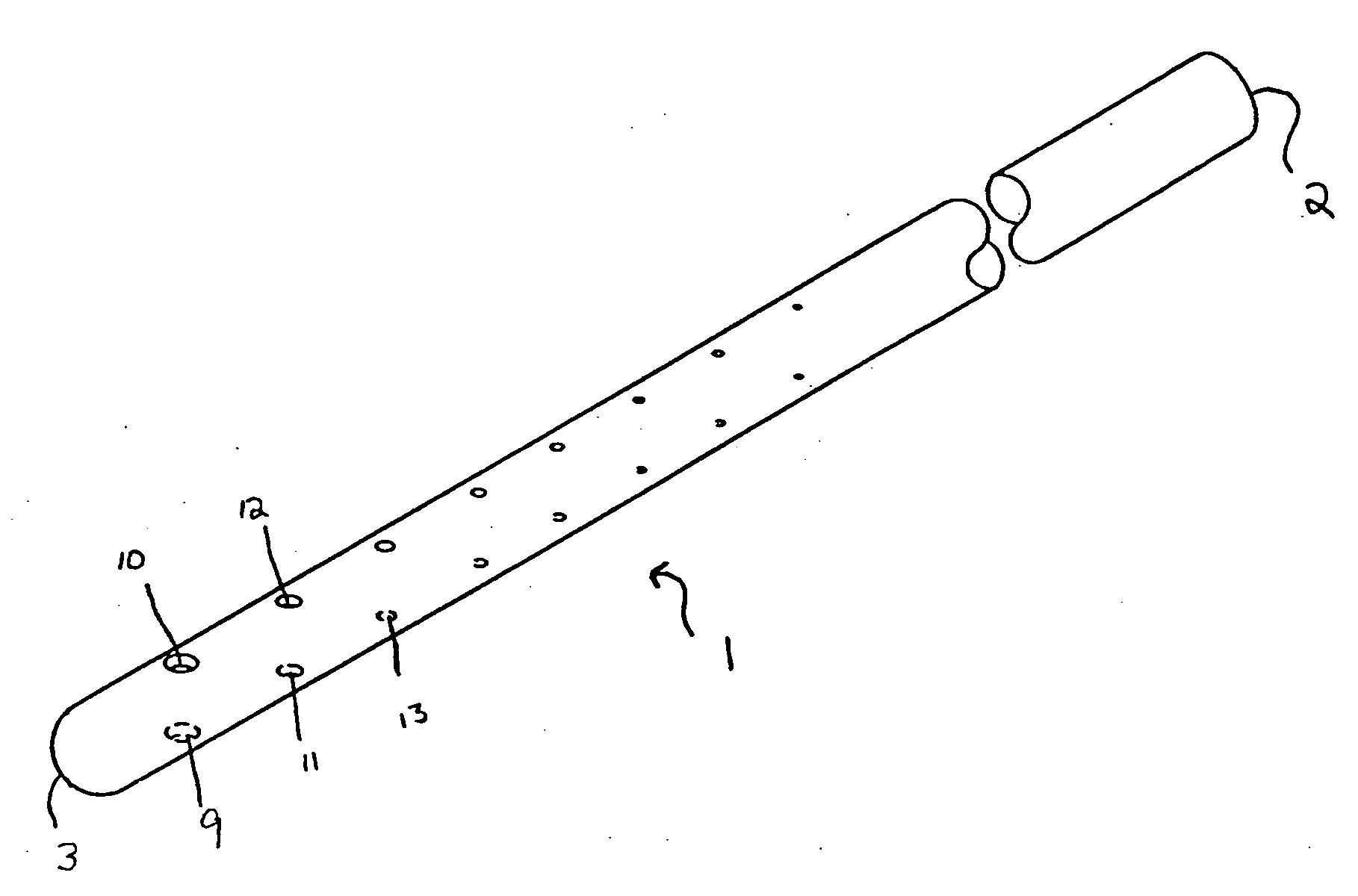
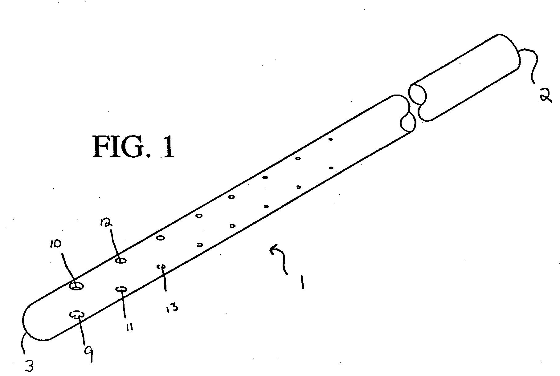
[0022] Drainage catheters can be improved by designs that force the fluid to be drained into a greater number of inlet holes. The present invention accomplishes this by progressively decreasing the cross-sectional areas of the inlet holes as the proximal end of the catheter is approached.

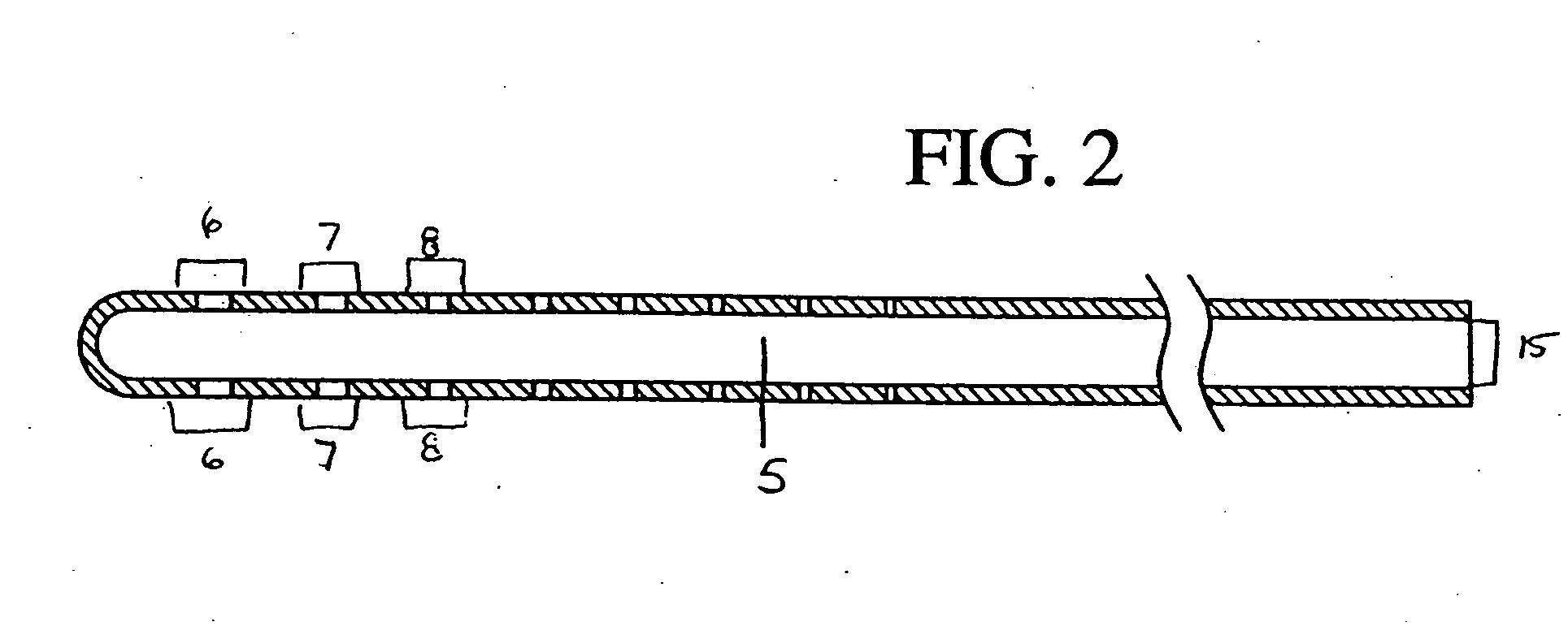
[0023]FIGS. 1-4 show a catheter 1 as an elongated tube in accordance with the present invention. The catheter 1 has a proximal end 2 and a distal end 3. The distal end 3 is adapted for implantation into a body cavity of an animal and the proximal end 2 is adapted for connection to means to divert fluid from that particular body cavity. The catheter 1 has an annular wall 4 that defines a central passageway 5. Along the...


PUM


Abstract

An improved drainage catheter having one or more inlet holes along the length of the catheter is described whereby the cross-sectional areas of the successive inlet holes decreases, the decrease first occurring at the inlet hole immediately following the most proximal inlet hole. This change in cross-sectional area alters the typical inflow of fluid into the catheter such that a disproportionately high volume of fluid no longer enters the most proximal inlet hole. This decrease in inflow at the most proximal inlet hole results in less deposition of debris within the catheter at that position. With less deposition of debris at this location, the likelihood of complete catheter failure is reduced. A preferred embodiment is described wherein the change in cross-sectional area results in approximately uniform inflow into all inlet holes.

Description

CROSS REFERENCE TO RELATED APPLICATIONS [0001] This application is a divisional of U.S. application Ser. No. 10 / 400,363, filed Mar. 26, 2003, the entire content of which is incorporated herein by reference, which claims priority from provisional application 60 / 367,565 filed on Mar. 26, 2002, which is incorporated in its entirety herein.BACKGROUND [0002] 1. Field of the Invention [0003] The present invention is a medical device, more particularly, a drainage catheter. [0004] 2. Discussion of the Prior Art [0005] Catheters of various types are used to drain fluid from a number of different areas within the bodies of animals. In some medical conditions, the flow rate of the fluid to be drained is quite low. As a result, the fluid inflow into the various inlet holes of catheters used to treat these conditions is also quite low. [0006] For example, one application of drainage catheters is to treat hydrocephalus, a medical condition that occurs when cerebrospinal fluid (“CSF”) builds up i...

Claims


Application Information

Patent Timeline
IPC IPC(8): A61M31/00A61M25/00A61M25/14
CPCA61M25/007A61M27/006A61M2025/0073
Inventor HURT, ROBERT F.
Owner MEDTRONIC PS MEDICAL
Why Eureka
Try Eureka