Speed reduction device of vehicle

a technology of speed reduction device and vehicle, which is applied in the direction of braking system, coupling, cycle, etc., can solve the problems of difficult to maintain the friction of balls, and achieve the effect of reducing the inclination angle of the drive shaft, maintaining the friction of the connection portion, and reducing the size of the connection portion

Inactive Publication Date: 2007-08-30
HONDA MOTOR CO LTD
View PDF6 Cites 16 Cited by
  • Summary
  • Abstract
  • Description
  • Claims
  • Application Information

AI Technical Summary

Benefits of technology

[0010]Accordingly, the speed reduction device includes a casing, and left and right drive axles which are rotatably mounted on the casing and are respectively connected to the left and right drive shafts. The driven sprocket to which the engine-side power is transmitted and the brake disc which constitutes a brake device for braking left and right drive axles are mounted on one of these left and right drive axles, and another of left and right drive axles is detachably mounted on one of left and right drive axles. Accordingly, it is possible to ensure the large total length of the drive shaft and hence, an inclination angle of the drive shaft can be decreased. Accordingly, a moving quantity of balls which are positioned in the inside of the connection portion of the left and right drive axles of the drive shafts can be decreased thus realizing the reduction in size of the connection portion. Further, the friction of the connection portion can be maintained at a low value over a long period.

Problems solved by technology

Further, it becomes difficult to maintain frictions of balls in the inside of the inner universal joint 10a and the outer universal joint 10b at small values for a long period.

Method used


Image

  • Speed reduction device of vehicle
  • Speed reduction device of vehicle
  • Speed reduction device of vehicle

Examples


Embodiment Construction

[0020]Hereinafter, an embodiment for carrying out the invention is explained in conjunction with attached drawings. Here, the drawings are observed in the direction of symbols.

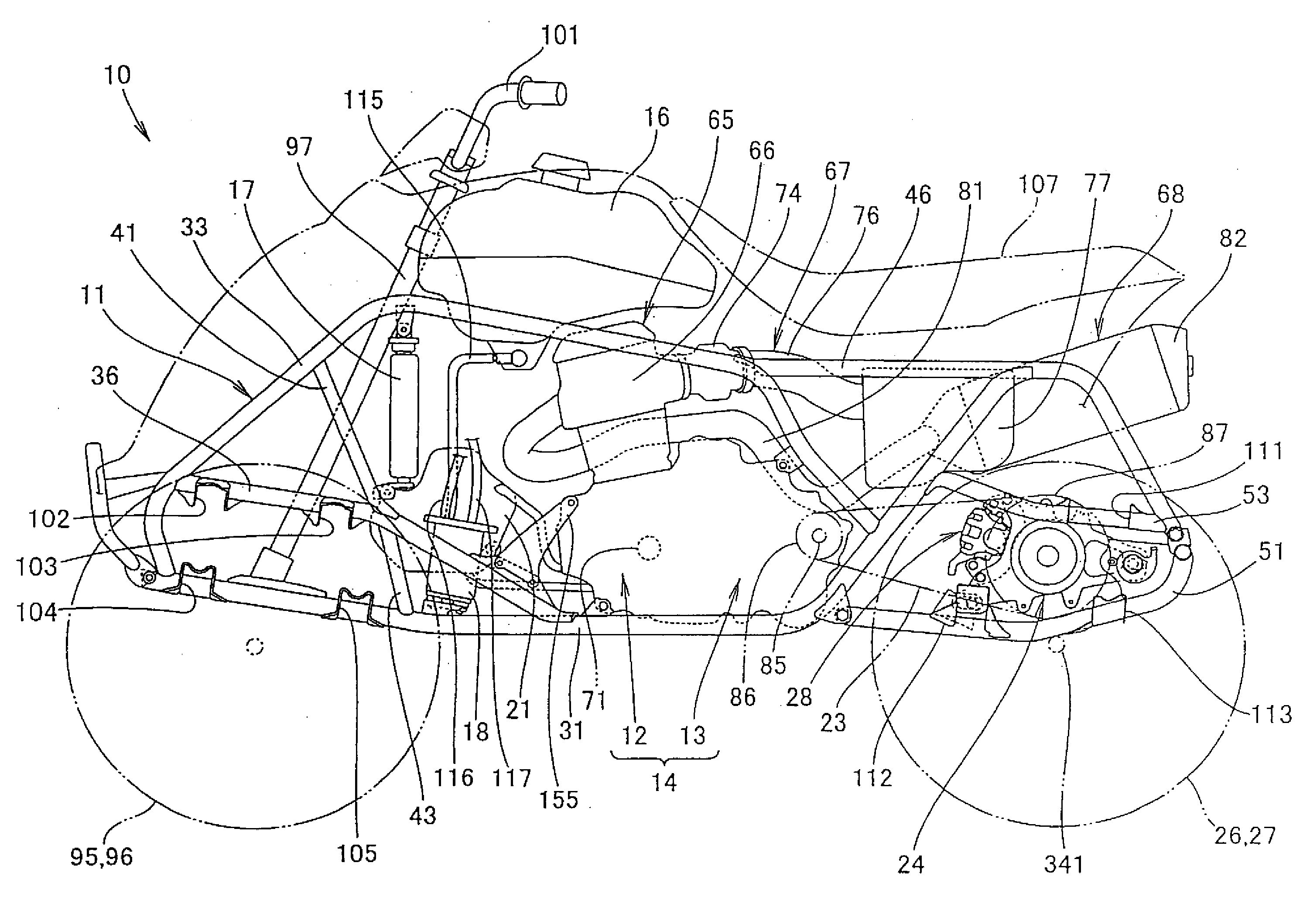
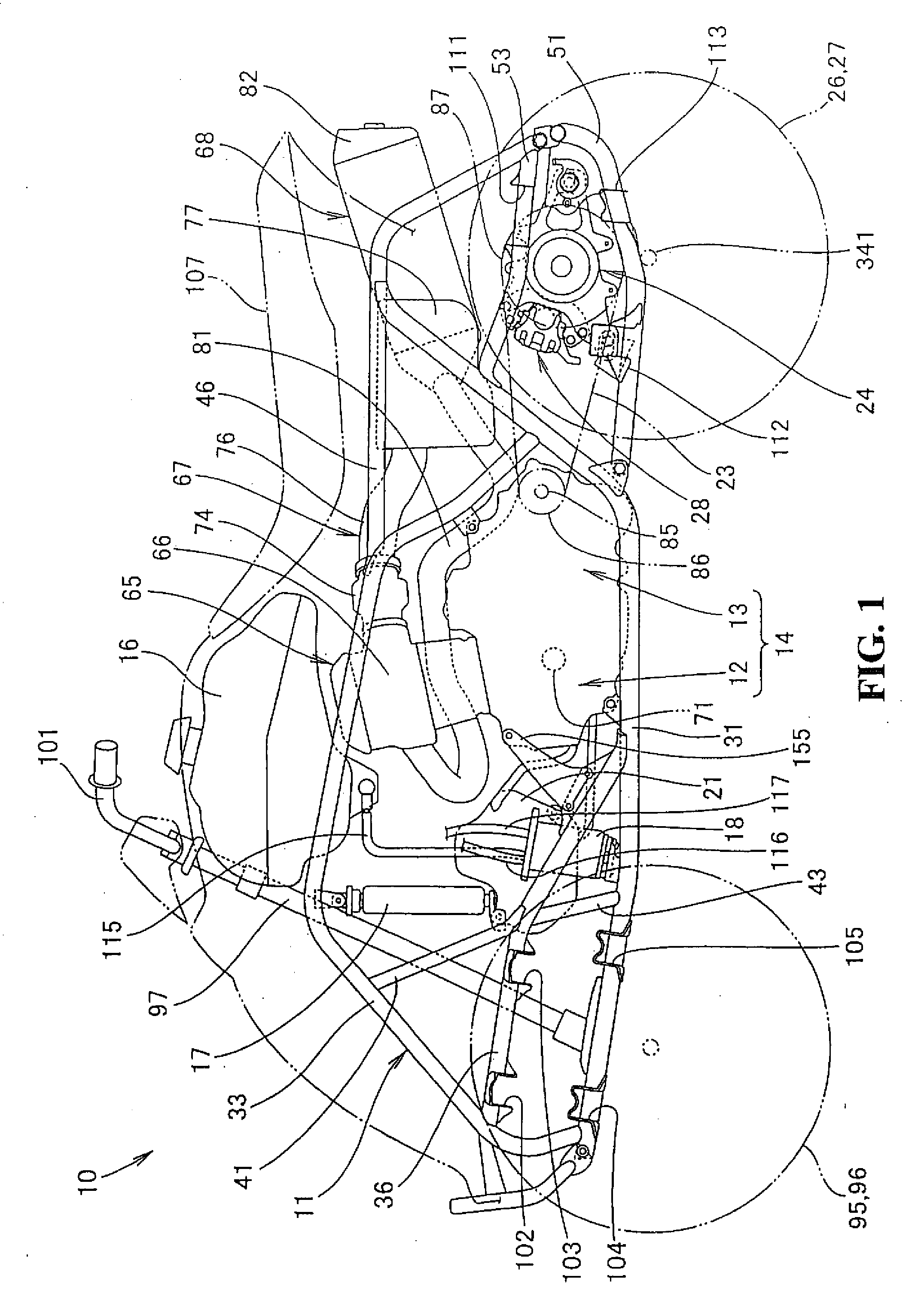
[0021]FIG. 1 is a side view of a vehicle according to the invention, wherein a vehicle 10 is a terrain traveling four-wheeled vehicle having the following constitution. A power unit 14 which is constituted of an engine 12 and a transmission 13 which is integrally formed with the engine 12 is mounted on a center portion of a vehicle body frame 11. A fuel tank 16 is positioned above the power unit 14. In a space below the fuel tank 16 and between the radiator 17 and the power unit 14, a fuel pump 18 which supplies fuel inside the fuel tank 16 to the engine 12 and an oil tank 21 which stores lubricant used in the inside of the power unit 14 are positioned. A speed reduction device 24 which transmits power via a chain 23 is positioned behind the power unit 14. A disc brake device 28 for braking left and right rear...


PUM


Abstract

A speed reduction device of a vehicle for reducing the rotation of drive wheels includes a casing mounted on a vehicle frame, first and second drive axles rotatably mounted on the casing and connected to first and second drive shafts, respectively, and a driven sprocket wheel and a brake disc for braking the first and second drive axles are mounted on the first drive axle. The second drive axle is detachably joined to the first drive axle.

Description

FIELD OF THE INVENTION [0001]The present invention relates to the improvement of a speed reduction device of a vehicle.BACKGROUND OF THE INVENTION [0002]As a conventional speed reduction device of a vehicle, there has been known a speed reduction device which includes a driven sprocket gear, a cylindrical member which supports the driven sprocket gear, and a cylindrical housing which rotatably supports the cylindrical member. See, for example, JP-A-63-90486 (JP '486).[0003]As shown in FIG. 1 of JP '486, the speed reduction device includes a cylindrical rear axle housing 8 which is mounted on a rear frame 6a of a vehicle body, a center rear axle 9 which is rotatably mounted on the rear axle housing 8 by way of ball bearings 19a, 19b, a detachable flange 16 which is integrally mounted on one end of the center rear axle 9, and a driven sprocket gear 12b which is mounted on the detachable flange 16.[0004]The center rear axle 9 is a member which has an outer peripheral portion of another...

Claims


Application Information

Patent Timeline
Patent Type & Authority Applications(United States)
IPC IPC(8): B62D21/00B60T1/06B62K5/00B62K5/01B62M17/00F16D3/20F16H57/02F16H57/023F16H57/035
CPCB62K5/027B62K5/01
Inventor SEKI, BUNZO
Owner HONDA MOTOR CO LTD
Why Eureka
Try Eureka